AD 2 Aerodromes
OTBD — DOHA INTL
OTBD AD 2.1 AERODROME LOCATION INDICATOR AND NAME
OTBD — DOHA INTL
OTBD AD 2.2 AERODROME GEOGRAPHICAL AND ADMINISTRATIVE DATA
| 1 | ARP coordinates and site at AD | 251539.81N 0513354.34E, Mid - point of RWY, on CL . | |||
| 2 | Direction and distance from (city) | 3.5 NM SE from Doha City Centre | |||
| 3 | Elevation/Reference temperature | 37 FT / 42.3° C | |||
| 4 | Geoid undulation at AD ELEV PSN | -98 FT | |||
| 5 | MAG VAR/Annual change | 2.6˚E (FEB 2020) / 0.03˚E | |||
| 6 | AD Operator, address, telephone, telefax, telex, AFS and website address | AD Operator: | Qatar Company for Airports Operation and Management - MATAR | ||
| Address: |
Chief Operating Officer
Hamad International Airport P.O. Box 24730 Doha State of Qatar |
||||
| Tel: | (974) 4010 7715 / (974) 4010 3999 | ||||
| Fax: | (974) 4010 1010 | ||||
| Email: | coohiaoffice@hamadairport.com.qa | ||||
| Website: | www.dohahamadairport.com | ||||
| SITA: | DOHAOXH | ||||
| 7 | Types of traffic permitted (IFR/VFR) | IFR / VFR | |||
| 8 | Remarks |
Airport Operations Control Centre Duty Manager (AOCC DM) 24/7:
|
|||
OTBD AD 2.3 OPERATIONAL HOURS
| 1 | AD Operator | H24 |
| 2 | Customs and immigration | H24 |
| 3 | Health and sanitation | H24 |
| 4 | AIS Briefing Office | H24 |
| 5 | ATS Reporting Office (ARO) | H24 |
| 6 | MET Briefing Office | H24 |
| 7 | ATS | H24 |
| 8 | Fuelling | On prior notification to fuel provider. See Item 10 of GEN 1.1 |
| 9 | Handling | On prior notification to ground handler. See Item 9 of GEN1.1 |
| 10 | Security | H24 |
| 11 | De-icing | Not required due to local climate |
| 12 | Remarks | NIL |
OTBD AD 2.4 HANDLING SERVICES AND FACILITIES
| 1 | Cargo-handling facilities | Available. (Qatar Aviation Services) |
| 2 | Fuel/oil types |
Fuel:
Jet A1 AVGAS 100 available only at Qatar Aeronautical College (QAC). Oil: NIL. |
| 3 | Fuelling facilities/capacity | On prior notification. See Item 10 of GEN 1.1 |
| 4 | De-icing facilities | Not required due to local climate. |
| 5 | Hangar space for visiting aircraft | NIL |
| 6 | Repair facilities for visiting aircraft | Contact QAS , see Item 9 of GEN 1.1 |
| 7 | Remarks | For handling facilities / services contact QAS , see Item 9 of GEN1.1 |
OTBD AD 2.5 PASSENGER FACILITIES
| 1 | Hotels | Hotel accommodation available in Doha City. |
| 2 | Restaurants | NIL |
| 3 | Transportation | NIL |
| 4 | Medical facilities | Full medical facilities available in Doha |
| 5 | Bank and Post Office | NIL |
| 6 | Tourist Office | NIL |
| 7 | Remarks | NIL |
OTBD AD 2.6 RESCUE AND FIRE FIGHTING SERVICES
| 1 | AD category for fire fighting | CAT 9 with CAT 10 available on request. Notification time to upgrade to CAT 10 will require a period of APRX 45 MIN . |
| 2 | Rescue equipment | As per ICAO Annex 14 and QCAR - ADR - Aerodrome Design, Operations and Licensing |
| 3 | Capability for removal of disabled aircraft | All aircraft types, Contact (974) 4018 4500 / 4018 4977 |
| 4 | Remarks | Communication with aircraft on ground available on 121.6 MHz |
OTBD AD 2.7 SEASONAL AVAILABILITY - CLEARING
| 1 | Types of clearing equipment | NIL |
| 2 | Clearance priorities | N/A |
| 3 | Remarks | Local climate precludes the requirement. Aerodrome is available in all seasons. |
OTBD AD 2.8 APRONS, TAXIWAYS AND CHECK LOCATIONS/POSITIONS DATA
| 1 | Designation, surface and strength of aprons |
MAIN APRON: concrete,
PCN
70 / R / A / X / T
VVIP APRON : concrete, PCN 70 / R / A / X / T WESTERN APRON: asphalt, PCN 70 / F/ A / X / U EASTERN APRON (1): concrete, PCN 70 / R / B / W / U EASTERN APRON (2): concrete, PCN 68 / R / B / W / T EASTERN APRON (3): concrete, PCN 70 / R / B / W / U EASTERN APRON (4): concrete, PCN 79 / R / A / W / T EASTERN APRON EXTENSION: concrete, PCN 63 / R / A / X / T RIZON APRON: asphalt, PCN 40 / F / B / X / U |
| 2 | Designation, width, surface and strength of taxiways |
TWY
A: 34 M, asphalt,
PCN
60 / F / A / X / T
TWY C: 23 M, asphalt, PCN 60 / F / A / X / T TWY D: 23 M, asphalt, PCN 60 / F / A / X / T TWY F: 26 M, asphalt, PCN 60 / F / A / X / T TWY P: 33 M, asphalt, PCN 70 / F / A / X / T TWY B, TWY E1, TWY E2, TWY G: 29 M, asphalt, PCN 60 / F / A / X / T TWY B1, TWY C1, TWY D1, TWY D3, TWY D4: 29 M, asphalt, PCN 70 / F / A / X / U TWY D2, TWY D2 EAST, TWY Z: 23 M, asphalt, PCN 72 / F / B / W / T TWY D2C: 18 M, asphalt, PCN 46 / F / B / W / U TWY U: 18 M, asphalt, PCN 40 / F / B / X / U TWY H, TWY J, TWY K, TWY L, TWY M, TWY N, TWY Q, TWY R, TWY S, TWY T, TWY Y: 23 M, asphalt, PCN 60 / F / A / X / T |
| 3 | Altimeter checkpoint location and elevation |
VVIP APRON – 36 FT
MAIN APRON – 23 FT WESTERN APRON – 30 FT EASTERN APRON (1) – 29 FT EASTERN APRON (2) – 21 FT EASTERN APRON (3) – 18 FT EASTERN APRON (4) – 16 FT |
| 4 | VOR checkpoints | N/A |
| 5 | INS checkpoints | See ACFT PARKING / DOCKING CHART |
| 6 | Remarks | ACFT Stands E1 to E10 and E12 to E17 (including MARS Stands) restricted to daytime operations only. |
OTBD AD 2.9 SURFACE MOVEMENT GUIDANCE AND CONTROL SYSTEM AND MARKINGS
| 1 | Use of aircraft stand ID signs, TWY guide lines and visual docking/parking guidance system at aircraft stands |
Aircraft Stand ID Signs and Visual Docking Guidance System ( VDGS ) are not available in all MARS Stands at Eastern Apron 1, 2, 3, Main Apron, VVIP Apron, Stands A1N, C1 to C9, G1, G2, G2P, G3, G4, E1 to E10, E12, E25 to E31. Parking with Follow Me vehicle only. Aircraft Stand ID Signs and Visual Docking Guidance System ( VDGS ) are operationally available at Stands A1 to A6, A9 to A18, E11, E13 to E24, E32 to E37, W6 and W7 Taxiing guidance signs at all intersections with TWY and RWY at all holding positions For information on Visual Docking Guidance System ( VDGS ) see OTBD AD 2.23.1 Visual Docking Guidance System |
| 2 | RWY and TWY markings |
RWY: designation,
THR
, displaced landing
THR
,
TDZ
,
CL
, edge, RWY end as appropriately marked
TWY : Edge, CL , holding positions at all TWY / RWY intersections marked |
| 3 | Stop bars | Stop bars at all RWY entrances and where appropriate except for TWY Q, TWY R and TWY S. |
| 4 | Remarks | TWY D2C: Taxiing to/from stands will be via follow-me vehicle. |
OTBD AD 2.10 AERODROME OBSTACLES
1 Obstacles in Area 2
2 Obstacles in Area 3
OTBD AD 2.11 METEOROLOGICAL INFORMATION PROVIDED
| 1 | Associated MET Office | DOHA MET OFFICE |
| 2 | Hours of service | H24 |
| MET Office outside hours | NIL | |
| 3 | Office responsible for TAF preparation | DOHA MET OFFICE |
| Periods of validity | 24 HR | |
| 4 | Type forecast | TREND |
| Interval of issuance | ½ HR | |
| 5 | Briefing/consultation provided | Personal consultation, partial self briefing, telephone to forecaster |
| 6 | Flight documentation | Charts, abbreviated plain language text |
| Language(s) used | English | |
| 7 | Charts and other information available for briefing or consultation | S, U 25 , P 25 , (other levels on request), T, SWH (East & West), SWM (MID), TB (Gulf sector winds) |
| 8 | Supplementary equipment available for providing information | Telefax |
| 9 | ATS units provided with information | DOHA TOWER, DOHA APPROACH |
| 10 | Additional information (limitation of service, etc.) | NIL |
OTBD AD 2.12 RUNWAY PHYSICAL CHARACTERISTICS
| Designations RWY NR | TRUE BRG | Dimensions of RWY (M) | Strength (PCN) and surface of RWY and SWY |
THR coordinates,
RWY end coordinates, THR geoid undulation |
THR elevation and highest elevation of TDZ of precision APP RWY |
|---|---|---|---|---|---|
| 1 | 2 | 3 | 4 | 5 | 6 |
| 15 | 158.15˚ | 4 570 x 46 |
60 / F / A / X / T
asphalt |
251626.13N
0513333.92E 251430.88N 0513424.73E -98.23 FT |
THR
34.75 FT
TDZ 34.75 FT |
| 33 | 338.16˚ | 4 570 x 46 |
60 / F / A / X / T
asphalt |
251430.88N
0513424.73E 251648.74N 0513323.95E -98.43 FT |
THR
26.96 FT
TDZ 27.32 FT |
| RWY NR | Slope of RWY- SWY | SWY dimensions (M) | CWY dimensions (M) | Strip dimensions (M) | RESA dimensions (M) | Location and Arresting System | OFZ | Remarks | |
|---|---|---|---|---|---|---|---|---|---|
| RWY | SWY | ||||||||
| 1 | 7 | 8 | 9 | 10 | 11 | 12 | 13 | 14 | |
| 15 | 0.11% first 1 524 M then 0.62% next 762 M then 0.00% next 914 M then 0.48% next 427 M then 0.15% next 945 M | NIL | NIL | 274 x 150 | 4 690 x 300 | 240 x 90 | NIL | Yes | Non load bearing shoulders 15 M |
| 33 | 0.15% first 945 M then 0.48% next 427 M then 0.00% next 914 M then 0.62% next 762 M then 0.11% next 1 524 M | NIL | NIL | 183 x 150 | 4 690 x 300 | 240 x 90 | NIL | Yes | Non load bearing shoulders 15 M |
OTBD AD 2.13 DECLARED DISTANCES
| RWY Designator | Intersection Departures | TORA (M) | TODA (M) | ASDA (M) | LDA (M) | Remarks |
|---|---|---|---|---|---|---|
| 1 | 2 | 3 | 4 | 5 | 6 | 7 |
| 15 | Not applicable | 4 570 | 4 844 | 4 570 | 3 820 | Threshold Displacement 750 M |
| TWY A | 3 821 | 4 095 | 3 821 | Not applicable | NIL | |
| TWY B | 3 058 | 3 332 | 3 058 | Not applicable | ||
| TWY B1 | 3 058 | 3 332 | 3 058 | Not applicable | ||
| TWY C1 | 2 516 | 2 790 | 2 516 | Not applicable | ||
| TWY C | 2 490 | 2 764 | 2 490 | Not applicable | ||
| TWY P | 2 451 | 2 725 | 2 451 | Not applicable | ||
| TWY E1 | 1 144 | 1 418 | 1 144 | Not applicable | ||
| TWY N | 1 144 | 1 418 | 1 144 | Not applicable | ||
| TWY E2 | 706 | 980 | 706 | Not applicable | ||
| TWY M | 706 | 980 | 706 | Not applicable | ||
| 33 | Not applicable | 4 570 | 4 753 | 4 570 | 4 570 | NIL |
| TWY F | 4 126 | 4 309 | 4 126 | Not applicable | ||
| TWY L | 4 126 | 4 309 | 4 126 | Not applicable | ||
| TWY K | 4 024 | 4 207 | 4 024 | Not applicable | ||
| TWY E2 | 3 890 | 4 073 | 3 890 | Not applicable | ||
| TWY M | 3 890 | 4 073 | 3 890 | Not applicable | ||
| TWY E1 | 3 450 | 3 633 | 3 450 | Not applicable | ||
| TWY N | 3 450 | 3 633 | 3 450 | Not applicable | ||
| LOOP | 2 482 | 2 665 | 2 482 | Not applicable | ||
| TWY C | 2 145 | 2 328 | 2 145 | Not applicable | ||
| TWY P | 2 145 | 2 328 | 2 145 | Not applicable | ||
| TWY B | 1 542 | 1 725 | 1 542 | Not applicable | ||
| TWY B1 | 1 542 | 1 725 | 1 542 | Not applicable | ||
|
Note: Intersection departures are allowed subject to the following:
|
||||||
OTBD AD 2.14 APPROACH AND RUNWAY LIGHTING
|
RWY
Designator |
APCH LGT type,
LEN, INTST |
THR LGT,
colour, WBAR |
VASIS
(MEHT) PAPI |
TDZ LGT
LEN |
RWY Centre Line LGT
Length, spacing, colour, INTST |
|---|---|---|---|---|---|
| 1 | 2 | 3 | 4 | 5 | 6 |
| 15 |
ICAO CAT I precision approach lighting system
900 M LIH |
Green supplemented by green WBAR |
PAPI 3.5˚
(67.3 FT) |
NIL |
Length: 4 570 M
Spacing: 15 M Colour: fm 0 M to last 900 M White, last 900 M to last 300 M Red / White, last 300 M Red INTST : LIH |
| 33 |
ICAO CAT II and III precision approach lighting system
900 M LIH |
Green supplemented by green WBAR |
PAPI 3˚
(69.2 FT) |
900 M |
Length: 4 570 M
Spacing: 15 M Colour: fm 0 M to last 900 M White, last 900 M to last 300 M Red / White, last 300 M Red INTST : LIH |
| RWY Designator |
RWY edge LGT
LEN, spacing, colour, INTST |
RWY End LGT
colour, WBAR |
SWY LGT
LEN, colour |
Remarks |
|---|---|---|---|---|
| 1 | 7 | 8 | 9 | 10 |
| 15 |
Length: 4 570 M
Spacing: 60 M Colour: fm 0 M to first 750 M Red, 750 M to last 600 M White, last 600 M Amber INTST : LIH |
Red
NIL |
NIL | On full length departures, the first 750 M of edge lights are Red due to DTHR |
| 33 |
Length: 4 570 M
Spacing: 60 M Colour: fm 0 M to last 600 M White, last 600 M Amber INTST : LIH |
Red
NIL |
NIL | NIL |
OTBD AD 2.15 OTHER LIGHTING, SECONDARY POWER SUPPLY
| 1 | ABN /IBN location, characteristics and hours of operation |
ABN : NIL IBN : NIL |
| 2 | LDI location and LGT | LDI : NIL |
| Anemometer location and LGT | Located at 251532.34N 0513352.83E ( APRX 124 M West of RCL and 58 M East of TWY D CL , ABM mid RWY turning pad); Lighted. | |
| 3 | TWY edge and centre line lighting |
Edge: All taxiway edge-Blue. Centre line: Green. |
| 4 | Secondary power supply/switch-over time |
Secondary power for CAT I / II / III Ops - on UPS immediate power and with battery backup for up to 30 minutes. Backup generator also available. Other lightings on backup generator.
Switch-over time: Switch over time within 15 seconds.
|
| 5 | Remarks |
NIL |
OTBD AD 2.16 HELICOPTER LANDING AREA
| 1 |
Coordinates TLOF or THR of FATO
Geoid undulation. |
NIL |
| 2 | TLOF and/or FATO elevation M/FT | NIL |
| 3 | TLOF and FATO area dimensions, surface, strength, marking | NIL |
| 4 | True BRG of FATO | NIL |
| 5 | Declared distance available | NIL |
| 6 | APP and FATO lighting | NIL |
| 7 | Remarks | As directed by ATC |
OTBD AD 2.17 ATS AIRSPACE
| 1 | Designation and lateral limits |
DOHA
CTR
:
253406.92N 0513740.03E - 253023.30N 0513919.31E then clockwise 20NM arc centred on 251020.20N 0513837.80E to 252814.44N 0514835.25E - 251255.01N 0515518.56E then clockwise 20NM arc centred on 251939.10N 0513431.60E to 250143.37N 0512438.00E - 245951.00N 0511930.00E - 250205.26N 0511830.70E then clockwise 5NM arc centred on 250705.86N 0511846.46E to 251032.49N 0511446.09E - 251510.00N 0511243.00E - 251703.32N 0511750.86E then clockwise 20NM arc centred on 251020.20N 0513837.80E to 252424.58N 0512254.19E - 252807.93N 0512115.03E then clockwise 20NM arc centred on 251403.80N 0513659.40E to 253406.92N 0513740.03E. |
| 2 | Vertical limits | SFC to 2 500 FT |
| 3 | Airspace classification | D |
| 4 |
ATS unit call sign
Language(s) |
DOHA Tower
English |
| 5 | Transition altitude | 13 000 FT |
| 6 | Hours of applicability | H24 |
| 7 | Remarks | NIL |
OTBD AD 2.18 ATS COMMUNICATION FACILITIES
| Service designation | Call sign | Frequencies allocation (MHz) |
Logon
address |
Hours of operation | Remarks |
|---|---|---|---|---|---|
| 1 | 2 | 3 | 4 | 5 | 6 |
| APP | Doha Radar North | 121.100 | N/A | H24 | Primary |
| 121.625 | N/A | H24 | Secondary | ||
| Doha Radar South | 120.675 As directed by ATC | N/A | H24 | Primary | |
| 119.150 As directed by ATC | N/A | H24 | Secondary | ||
| Doha Approach West | 119.725 | N/A | H24 |
Primary
|
|
|
125
|
N/A | H24 | Secondary | ||
| Doha Approach East | 124.775 As directed by ATC | N/A | H24 | Primary | |
| 120.600 As directed by ATC | N/A | H24 | Secondary | ||
| Doha Director East | 119.400 | N/A | H24 | Primary | |
| 121.125 | N/A | H24 | Secondary | ||
| Doha Director West | 123.875 As directed by ATC | N/A | H24 | Primary | |
| 119.225 As directed by ATC | N/A | H24 | Secondary | ||
| Doha Director | 124.050 As directed by ATC | N/A | H24 | Primary | |
| 121.775 As directed by ATC | N/A | H24 | Secondary | ||
| - | 121.500 | N/A | H24 | Emergency | |
| - | 243.000 | N/A | H24 | Emergency | |
| TWR | Doha Tower | 118.900 | N/A | H24 | Primary |
| - | 119.025 | N/A | H24 | Secondary | |
| - | 121.500 | N/A | H24 | Emergency | |
| - | 243.000 | N/A | H24 | Emergency | |
| GMC Vehicle | Doha Ground | 121.800 | N/A | H24 | Vehicles only |
| GMC | Doha Ground | 121.925 | N/A |
Daily 0400 - 2200 during peak traffic conditions or may be changed according to ATC requirements |
All TFC DEP OTBD for push back, start - up & taxi clearance |
| D-ATIS | Doha Terminal Information | 126.450 | DOHAAYA | H24 |
Data Link Service available. ATIS broadcast can also be obtained via hotline: (974) 44656213 |
| DCL | N/A | N/A | DOHCAYA | H24 | Data Link Service for departure clearance |
|
Note
:
|
|||||
OTBD AD 2.19 RADIO NAVIGATION AND LANDING AIDS
|
Type of Aid, MAG VAR,
Type of supported OPS (for VOR/ILS/MLS, give declination) |
IDENT | Frequency | Hours of operation | Position of transmitting antenna coordinates | Elevation of DME transmitting antenna | Remarks |
|---|---|---|---|---|---|---|
| 1 | 2 | 3 | 4 | 5 | 6 | 7 |
|
DVOR
|
DIA |
112.400 MHz |
H24 |
251402.23N
|
NIL | |
|
DME |
DIA |
CH 71X |
H24 |
251402.30N
|
44.82 FT | Co-located with ‘DIA’ DVOR |
|
LOC
RWY 33
ILS
|
IBD |
109.500 MHz |
H24 |
251657.65N
|
336˚ MAG 2.63 NM fm
THR
RWY 33,
ELEV 40.39 FT |
|
|
GP RWY 33 |
332.600 MHz |
H24 |
251442.20N
|
GP Angle 3˚
RDH 52 FT |
||
|
ILS DME RWY 33 |
IBD |
CH 32X |
H24 |
251442.22N
|
47.40 FT | Co - located with GP , DIST zero TDZ |
|
MM RWY 33 |
75 MHz |
H24 |
251358.46N
|
156˚ MAG 0.58 NM fm THR RWY 33 | ||
|
LOC
RWY 15
ILS
|
AMD |
108.500 MHz |
H24 |
251419.23N
|
LOC RWY 15 not usable beyond 17 DME from ‘AMD’ | |
|
GP RWY 15 |
329.900 MHz |
H24 |
251617.94N
|
GP
Angle 3.5˚
RDH 60 FT |
||
|
ILS DME RWY 15 |
AMD |
CH 22X |
H24 |
251617.95N
|
90.52 FT | Co - located with GP , DIST zero TDZ . |
|
L
|
WK |
323 KHz |
H24 |
251053.05N
|
156˚ MAG 3.90 NM fm THR RWY 33 |
OTBD AD 2.20 LOCAL AERODROME REGULATIONS
1 Airport regulations
- Flight over Doha City prohibited below 2 000 FT unless authorized by ATC .
- Flight over QEAF Airbase below 1 500 FT prohibited at all times.
- Voluntary reporting of any defect, fault, safety hazard, safety accident, serious incidents and occurrence should be reported to the aerodrome operator on the following email: safetyreports@hamadairport.com.qa
2 Taxiing to and from stands
3 Parking area for small aircraft (General aviation)
4 Parking area for helicopters
5 Apron — taxiing during winter conditions
6 Taxiing — limitations
7 School and training flights — technical test flights — use of runways
8 Helicopter traffic — limitation
9 Removal of disabled aircraft from runways
OTBD AD 2.21 NOISE ABATEMENT PROCEDURES
OTBD AD 2.22 FLIGHT PROCEDURES
1 Special procedures applicable to ILS category II / III operations at DOHA INTERNATIONAL
1.1 General
OTBD: RWY 33, CAT II or CAT III
1.2 Authorization
Operators will be permitted to execute CAT II / III approaches and landings if they are legally authorized by their own state of registration to do so, and after having conveyed a copy of their relevant certification papers to the:
| Post: |
President
Civil Aviation Authority P.O. Box 3000 Doha State of Qatar |
And obtaining endorsement of acceptance there from.
2 Low visibility procedures (LVP)
3 PROCEDURES TO BE OBSERVED BY VFR AIRCRAFT IN AND OUT OF DOHA CONTROL ZONE
3.1 GENERAL
3.2 CIVIL ROTARY WING AIRCRAFT
| VFR Rep Points | Designator | Coordinates | |
|---|---|---|---|
| ASPIRE | ASP | 251544.78N | 0512641.36E |
| BANANA EAST | BNE | 251850.49N | 0514140.25E |
| THUMAMA | THM | 251344.29N | 0513120.70E |
| BAY-POINT | BAY | 251923.40N | 0513802.40E |
| BOAT | BOT | 253319.71N | 0513801.01E |
| TAWAR | TAW | 252010.10N | 0512851.94E |
| CENTRAL ROUNDABOUT | CRA | 251531.20N | 0513503.57E |
| DHOW | DOW | 251245.63N | 0515515.32E |
| DUNE | DNE | 250546.19N | 0513600.94E |
| FALCON | FCN | 252857.13N | 0512728.62E |
| HAB | HAB | 252554.00N | 0514112.60E |
| HAMAMA | HMM | 252653.28N | 0512435.68E |
| EZDAN | EZD | 251957.53N | 0512744.74E |
| MARRIOT | MRT | 251800.58N | 0513357.07E |
| NORTH ROUNDABOUT | NRA | 251623.55N | 0513438.06E |
| ORYX | ORX | 252647.00N | 0512514.03E |
| SEA-POINT | SEA | 251600.00N | 0513925.80E |
| SBAQ | SBQ | 252922.58N | 0512709.46E |
| SOUTH ROUNDABOUT | SRA | 251423.05N | 0513528.92E |
| RADISSON | RDS | 251619.73N | 0513049.22E |
| TURTLE | TTL | 253251.76N | 0513813.34E |
| QARN | QRN | 253152.78N | 0512650.29E |
| VILLAGE | VLG | 251558.26N | 0513005.72E |
| ZULU | ZUL | 251255.01N | 0512700.43E |
3.2.2.1 Civil Rotary Wing Aircraft departing from OTBD.
| Runway | Name | Description | |
|---|---|---|---|
|
Note: The HELI SOUTH Route is restricted to periods when the visibility is 5000 M or greater. Below 5000 M the HELI SOUTH Route is not available except for Gulf Helicopters Company which can operate VFR in this route when visibility is greater than 3500 M. |
|||
| a) | RWY 15 | RED ROUTE |
After departure
RWY
15, turn right direct RDS and climb to
1000 FT. From RDS, route direct TAW. After TAW, climb to 1500 FT and
route ORX, FCN, TTL. After TTL, resume own navigation.
Note: After ORX aircraft may request direct routing to QRN for shorter routing to destination. After QRN, resume own navigation. |
| b) | RWY 33 | RED ROUTE |
After departure
RWY
33, turn left direct RDS and climb to
1000 FT. From RDS, route direct TAW. After TAW, climb to 1500 FT and
route ORX, FCN, TTL. After TTL, resume own navigation.
Note: After ORX aircraft may request direct routing to QRN for shorter routing to destination. After QRN, resume own navigation. |
| c) | RWY 33 | HELI 33 SOUTH | After departure RWY 33, turn left towards THM climbing to altitude 1500 FT. From THM, route DNE, then DOW. Aircraft to monitor Hamad TWR East on FREQ 118.525 MHz between DNE and DOW. From DOW, aircraft will resume own navigation. |
3.2.2.2 Civil Rotary Wing Aircraft departing from OTBD crossing OTHH. The following routes are subject to OTHH ATC approval when visibility is 5000 M or greater and only available for aircraft outbound on radials between DOH VOR R020 and DOH VOR R080.
| Runway | Name | Description | |
|---|---|---|---|
| a) | RWY 15 | BAY-POINT (BAY) Departure | After departure RWY 15, turn left towards CRA and climb to cross CRA maintaining 1000 FT. Contact Hamad TWR West on FREQ 118.025 MHz once East of OTBD RWY 15. From CRA, route to MRT and Hold, remaining clear of final approach path OTBD RWY 15 and OTHH RWY 16R whilst awaiting crossing clearance from OTHH ATC . When cleared, cross North of threshold OTHH RWY 16R/ RWY 16L and route towards BAY. After BAY, aircraft will resume own navigation and ATC will instruct aircraft to climb to 1500 FT as soon as practicable. |
| b) | RWY 33 | SEA-POINT (SEA) Departure | After departure RWY 33, turn right towards CRA and climb to cross CRA maintaining 1000 FT. Contact Hamad TWR West on FREQ 118.025 MHz once East of OTBD RWY 33. From CRA, route to SRA and Hold, remaining clear of final approach path OTBD RWY 33 and OTHH RWY 34L whilst awaiting crossing clearance from OTHH ATC . When cleared, cross South of threshold OTHH RWY 34L/ RWY 34R and route towards SEA. After SEA, aircraft will resume own navigation and ATC will instruct aircraft to climb to 1500 FT as soon as practicable. |
3.2.3.1 Civil Rotary Wing Aircraft arriving to OTBD.
| Runway | Name | Description | |
|---|---|---|---|
|
Note 1: The HELI 33 SOUTH Route is restricted to periods when the visibility is 5000 M or greater. Below 5000 M the HELI 33 SOUTH Route is not available except for Gulf Helicopters Company which can operate VFR in this route when visibility is greater than 3500 M. Note 2: When visibility is less than 5000 M and greater than 3500 M, the BLUE Route is suspended, and the GREEN Route becomes active. Note 3: Aircraft inbound on these routes must call OTBD tower on FREQ 118.900 MHz 10 MIN before entering the CTR for joining clearance. |
|||
| a) |
RWY
15
and RWY 33 |
BLUE ROUTE |
Enter the
CTR
via BOT maintaining 1000 FT. From BOT,
route SBQ, HMM, EZD, VLG. From VLG, follow instructions from OTBD
ATC
.
Aircraft may request to enter the CTR via QRN. If approved, aircraft must maintain 1000 FT at QRN and then route HMM to join the BLUE ROUTE. |
| b) |
RWY
15
and RWY 33 |
GREEN ROUTE |
Enter the
CTR
via BOT maintaining 1000 FT. From BOT,
route SBQ, HMM, ASP, THM. From THM, follow instructions from OTBD
ATC
.
Aircraft may request to enter the CTR via QRN. If approved, aircraft must maintain 1000 FT at QRN and then route HMM to join the GREEN ROUTE. |
| c) | RWY 33 | HELI 33 SOUTH |
Route DOW and cross the
CTR
boundary maintaining 1000 FT. From DOW,
route DNE, THM. After THM, follow instructions from OTBD
ATC
.
Aircraft are required to monitor OTHH TWR East on FREQ 118.525 MHz between DOW and DNE. |
3.2.4.2 Civil Rotary Wing Aircraft arriving to OTBD. The following routes are subject to OTHH ATC approval when visibility is 5000 M or greater and only available for inbound from radials between DOH VOR R020 and DOH VOR R080.
| Runway | Name | Description | |
|---|---|---|---|
|
Note: All aircraft inbound to OTBD via these routes shall contact OTHH Tower East on FREQ 118.525 MHz at least 10 MIN before entering the CTR . |
|||
| a) | RWY 15 | BAY-POINT (BAY) Arrival | Cross the CTR boundary maintaining 500 FT and route direct BAY to hold awaiting instructions from OTHH TWR East on FREQ 118.525 MHz. Once cleared, cross North of threshold OTHH RWY 16L/ RWY 16R towards MRT and hold. Follow instructions from OTBD ATC . Contact OTBD ATC on FREQ 118.900 MHz once West of OTHH RWY 16R. |
| b) | RWY 33 | SEA-POINT (SEA) Arrival | Cross the CTR boundary maintaining 500 FT and route direct SEA to hold awaiting instructions from OTHH TWR East on FREQ 118.525 MHz. Once cleared, cross south of threshold OTHH RWY 34R/ RWY 34L towards SRA and hold. Follow instructions from OTBD ATC . Contact OTBD ATC on FREQ 118.900 MHz once West of OTHH RWY 34L. |
3.2.5.1 All traffic operating Special VFR (SVFR) will use the BLUE Route for inbound and RED Route for outbound. Delays may be expected.
3.2.6.1 Rotary wing aircraft shall use the active runway for take-off and landing.
3.2.6.2 Aircraft will air taxi/ground taxi (Depending on type) to the assigned gate using taxiways as instructed by ATC .
3.2.7.1. Aircraft to squawk RCF and follow the BLUE Route. From VLG, route to land at OTBD using the runway at pilot’s discretion and observe traffic patterns.
3.3 CIVIL FIXED WING AIRCRAFT
| VFR Rep Points | Designator | Coordinates | |
|---|---|---|---|
| ALPHA | ALF | 252344.84N | 0512204.72E |
| ASPIRE | ASP | 251544.78N | 0512641.36E |
| THUMAMA | THM | 251344.29N | 0513120.70E |
| RADISSON | RDS | 251619.73N | 0513049.22E |
| CENTRAL ROUNDABOUT | CRA | 251531.20N | 0513503.57E |
| SHAMAL | SML | 253716.55N | 0512405.05E |
| SOFIA | SOF | 252425.00N | 0512254.00E |
| SOUTH POINT | SPT | 245917.99N | 0513111.90E |
| ZULU | ZUL | 251255.01N | 0512700.43E |
3.3.2.1 Aircraft departing from OTBD to the North.
| Runway | Name | Description | |
|---|---|---|---|
| a) | RWY 33 | ASPIRE 33 Visual Departure | Climb straight ahead to 700 FT, turn to the West and remain clear of prohibited area OTP45; route direct to ASP then direct to SOF; then direct to SML. Climb as instructed by ATC to 1500 FT. |
| b) | RWY 15 | ASPIRE 15 Visual Departure | Climb straight ahead to 700 FT turn to the West before the upwind end of RWY 15; route direct to THM, direct to ASP, direct to SOF then direct to SML. Climb as instructed by ATC to 1500 FT. |
3.3.3.1 Civil Fixed Wing Aircraft arriving to OTBD from the North.
| Runway | Name | Description | |
|---|---|---|---|
|
Note 1: Aircraft to contact Doha TWR at SML for inbound clearance. Note 2: If more than two aircraft requesting to return to Doha from General Flying Area, and they will be required to Hold overhead ZUL for RWY 33 or VLG for RWY 15, succeeding aircraft will be advised to remain clear of the CTR and standby for joining instruction. Only one aircraft may hold at any one time over ZUL and VLG respectively. No Holding allowed overhead ASP. Note 3: VFR traffic arriving on the ASP arrival are independent of OTHH IFR traffic. Note 4: Aircraft proceeding to right base RWY 15 from VLG will maintain 1500 FT until established on final approach to avoid infringing the restricted area over the Amiri Diwan. After establishing the approach, touchdown may be expected approximately abeam intersection TWY Q, with roll-out and vacation at intersection TWY B or TWY B1. Note 5: Advanced students or instructors may be able to accomplish touchdown and roll-out earlier than the above, but no attempt should be made to request this from the pilot. |
|||
| a) | RWY 33 | ASPIRE 33 Visual Arrival | From SML, route direct to SOF traffic must be 2000 FT at SOF. Then route direct to ASP and hold over ASP as required by ATC . From ASP, route direct to ZUL if requested. Hold at ZUL at 2000 FT. From ZUL, route direct to THM and descend as instructed by ATC . Hold overhead THM at 1500 FT. When instructed by ATC, route for final approach RWY 33. |
| b) | RWY 15 | ASPIRE 15 Visual Arrival | From SML, route direct to SOF. Traffic must be 2000 FT by SOF, then route direct to ASP and hold over ASP as required by ATC . When cleared by ATC , proceed to VLG and descend to 1500 FT. |
3.3.4.1 VFR circuit training will be conducted on the OTHH Western RWY . Only when the Western RWY is closed will VFR aircraft operate on the Eastern RWY .
3.3.4.2 After Touch and Go, aircraft can expect turn to the West unless otherwise instructed by ATC .
3.3.4.3 It is the Pilot’s responsibility to remain clear of restricted areas.
3.3.4.4 The VFR downwind for OTHH Western and Eastern RWY is 1000 FT along the Ras Abu Aboud Road.
4 VFR RADIO COMMUNICATION FAILURE PROCEDURE
4.1 Rotary Wing
4.2 Fixed Wing
Procedures to be observed by VFR aircraft in and out of Doha Control Zone
3.2.1 Reporting points for Civil Rotary Wing aircraft:
| BANANA EAST (BNE) | 251850.49N 0514140.25E |
| BAY-POINT (BAY) | 251923.40N 0513802.40E |
| CABLE (CAB) | 252922.58N 0512709.46E |
| CENTRAL ROUNDABOUT (CRA) | 251531.20N 0513503.57E |
| HAB (HAB) | 252554.00N, 0514112.60E |
| LANDMARK (LMK) | 251954.21N 0512751.49E |
| MARRIOT (MRT) | 251800.58N 0513357.07E |
| NORTH ROUNDABOUT (NRA) | 251623.55N 0513438.06E |
| OUTER CHANNEL MARKER (OCM) | 251602.64N 0514418.28E |
| ROMEO (RME) | 251619.73N 0513049.22E |
| SARAH (SRH) | 252653.28N 0512435.68E |
| SEA-POINT (SEA) | 251600.00N 0513925.80E |
| SOUTH ROUNDABOUT (SRA) | 251423.05N 0513528.92E |
| SOUTH POINT 1 (SP1) | 250546.19N 0513600.94E |
| SOUTH POINT 2 (SP2) | 251245.63N 0515515.32E |
| SPOON (SPN) | 253319.71N 0513801.01E |
| X-RAY (XRY) | 251344.29N 0513120.70E |
| ZULU (ZUL) | 251255.01N 0512700.43E |
3.2.2 Reporting points for Civil Fixed Wing aircraft:
| ALPHA (ALF) | 252344.84N 0512204.72E |
| ASPIRE (ASP) | 251544.78N 0512641.36E |
| BRAVO (BVO) | 253201.18N 0511823.86E |
| ROMEO (RME) | 251619.73N 0513049.22E |
| SHAMAL (SML) | 253716.55N 0512405.05E |
| SOFIA (SOF) | 252425.00N 0512254.00E |
| SOUTH POINT (SPT) | 245917.99N 0513111.90E |
| X-RAY (XRY) | 251344.29N 0513120.70E |
| ZULU (ZUL) | 251255.01N 0512700.43E |
3.5.1 Aircraft departing from Doha International Airport
| Runway | Name | Description | |
|---|---|---|---|
|
Note: The HELI SOUTH ROUTE is restricted to periods when the visibility is 5000 M or greater. Below 5000 M the HELI SOUTH route is not available except for Gulf Helicopters which can operate VFR down to 3500 M visibility. |
|||
| a) | RWY 15 | HELI SPOON 15 Departure | After departure RWY 15, turn right to X-RAY (XRY) and climb to 1500 FT. From XRY, route direct LANDMARK (LMK), then SARAH (SRH), CABLE (CAB) and SPOON (SPN). After SPN, aircraft will be routed as requested. |
| b) | RWY 33 | HELI SPOON 33 Departure | After departure RWY 33 turn left route ROMEO (RME) and climb to 1500 FT. From RME, route direct LANDMARK (LMK), then SARAH (SRH), CABLE (CAB) and SPOON (SPN). After SPN, aircraft will be routed as requested. |
| c) | RWY 33 | HELI SOUTH 33 Departure | After departure RWY 33 turn left towards X-RAY (XRY) climbing to altitude 1500 FT. From XRY helicopters route direct SOUTH POINT 1 (SP1). Aircraft to monitor Hamad TWR East Frequency 118.525 MHz until reaching SOUTH POINT 2 (SP2). |
| Runway | Name | Description | |
|---|---|---|---|
|
Note: From BNE, the following outbound procedures will apply:
|
|||
| a) | RWY 15 | BAY-POINT (BAY) Departure |
After departure RWY 15, turn left towards
CENTRAL ROUNDABOUT (CRA) and climb to 1000 FT to cross CRA at 1000 FT,
contact Hamad TWR West (TW) once clear of RWY. From CRA route to MARRIOT
(MRT) and Hold, whilst awaiting clearance from
ATC
. When cleared, cross North of threshold
RWY 16R/RWY 16L and route towards BAY-POINT (BAY) and BANANA EAST (BNE).
(See note below)
Note: The aircraft should not, in normal circumstances, leave MRT until TW has effected coordination with Tower East (TE) and all Traffic Information (TI) passed i.e. RWY 16R/RWY 16L traffic, helicopter arrivals etc. |
| b) | RWY 33 | SEA-POINT (SEA) Departure |
After departure RWY 33 turn right towards
CENTRAL ROUNDABOUT (CRA) and climb to 1000 FT to cross CRA at 1000 FT,
contact Hamad Tower West (TW) once clear of RWY. From CRA route to SOUTH
ROUNDABOUT (SRA) and Hold, whilst awaiting clearance from
ATC
. When cleared, cross south of threshold
RWY 34L/RWY 34R and route towards SEA-POINT (SEA) and BANANA EAST (BNE).
(See note below).
Note: The aircraft should not, in normal circumstances, leave SRA until TW has effected coordination with Tower East (TE) and all Traffic Information (TI) passed i.e. RWY 34L/RWY 34R traffic, helicopter arrivals etc. |
3.5.2 Aircraft inbound to Doha International Airport
| Runway | Name | Description | |
|---|---|---|---|
|
Note1: Aircraft to contact Doha TWR 10 minutes before entering the CTR . Note2: The HELI SOUTH ROUTE is restricted to periods when the visibility is 5000 M or greater. Below 5000 M the HELI SOUTH route is not available except for Gulf Helicopters which can operate VFR down to 3500 M visibility. |
|||
| a) | RWY 15 | HELI SPOON 15 Arrival | Aircraft will route direct SPOON (SPN) to cross SPN maintaining 1000 FT and then route CABLE (CAB), SARAH (SRH), LANDMARK (LMK) and Hold overhead ROMEO (RME) if required. From RME, route as cleared by ATC for right base RWY 15. |
| b) | RWY 33 | HELI SPOON 33 Arrival | Aircraft will route direct SPOON (SPN) to cross SPN maintaining 1000 FT and then route CABLE (CAB), SARAH (SRH), LANDMARK (LMK) then direct X-RAY (XRY) hold overhead XRY if required. From XRY, route as cleared by ATC for landing RWY 33. |
| c) | RWY 33 | HELI SOUTH 33 Arrival | Aircraft will enter via SOUTH POINT 2 (SP2) at 1000 FT and is required to pass estimate for SOUTH POINT 1 (SP1) and the POB to Doha TWR on 118.9 MHz. Aircraft to monitor Hamad TWR East Frequency 118.525 MHz. At SOUTH POINT 1 (SP1), helicopters to contact Doha TWR 118.9 MHz for joining instructions. |
| Aircraft inbound from the North and the East |
|---|
All aircraft inbound to Doha International
Airport shall contact Hamad Tower East (TE) at least 10 minutes before
entering the
CTR
. Once cleared by
ATC
, the aircraft will route as below and arrange to cross the
CTR
boundary at 500 FT.
|
| Runway | Name | Description | |
|---|---|---|---|
| a) | RWY 15 | BAY-POINT (BAY) Arrival | When cleared to leave BANANA-EAST (BNE), aircraft will be tactically routed to Hold at BAY-POINT (BAY). Aircraft should not, in normal circumstances, leave the BAY Hold until TE has effected coordination with TW and all traffic information passed i.e. RWY 16L/RWY 16R traffic, helicopter departures, etc. Doha TWR should also be informed. From BAY, aircraft should route North of threshold RWY 16L/RWY 16R towards MRT and join long final RWY 15. Once clear of the Eastern RWY, aircraft should be passed traffic information as necessary and transferred to Doha TWR (or TW if they request it during coordination). Helicopter may be requested to Hold at MRT if, required due to traffic on final RWY 15. |
| b) | RWY 33 | SEA-POINT (SEA) Arrival | When cleared to leave BANANA-EAST (BNE), aircraft will be tactically routed to Hold at SEA. Aircraft should not, in normal circumstances, leave the SEA-POINT (SEA) hold until TE has effected coordination with TW and all traffic information passed i.e. RWY 34R/RWY 34L traffic, helicopter departures, etc. Doha TWR should also be informed. From SEA, aircraft should route South of threshold RWY 34R/RWY 34L towards SRA. Once clear of the Eastern RWY, aircraft should be passed traffic information as necessary and transferred to Doha TWR (or TW if they request it during coordination). Helicopter may be requested to Hold at SRA if required due to traffic on final RWY 33. |
3.5.3 Special VFR operations
3.5.4 Radio Communication Failure during VMC .
| Aircraft east of a line drawn between MRT and SRA. |
| Aircraft outside the CTR will route direct to BANANA EAST (BNE) and Hold for 3 minutes. There after the aircraft will route either to BAY or SEA depending on Runway-in-use and execute 2 Holds and visually check the landing area and the TWR for visual signals. Aircraft will then proceed and land on the RWY 34R/16L close to TWY A6, or if runway block land on TWY B. |
| Aircraft west of a line drawn between MRT and SRA. |
| Remain west of this line, Hold on western side of RWY 15/33 and observe TWR for visual signals. After 3 minutes proceed to land on Runway-in-use in Doha. |
3.6.1 Aircraft departing from Doha to the North
| Runway | Name | Description | |
|---|---|---|---|
| a) | RWY 33 | ASPIRE 33 Visual Departure | Climb straight ahead to 700 FT, turn to the West and remain clear of prohibited-area OTP45; route direct to ASPIRE (ASP); then direct to point SOFIA (SOF); then direct to point SHAMAL (SML). Climb as instructed by ATC to 1500 FT. |
| b) | RWY 15 | ASPIRE 15 Visual Departure | Climb straight ahead to 700 FT turn to the West before the upwind end of RWY 15; route direct to point X-RAY (XRY); direct to ASPIRE (ASP); direct to point SOFIA (SOF); then direct to point SHAMAL (SML). Climb as instructed by ATC to 1500 FT. |
3.6.2 Aircraft inbound to Doha from the North
| Runway | Name | Description | |
|---|---|---|---|
| a) | RWY 33 | ASPIRE 33 Visual Arrival | From point SHAMAL (SML), route direct to SOFIA (SOF) traffic must be 2000 FT at SOF then route direct to ASP and hold over ASP as required by ATC . From ASP, route direct to ZULU (ZUL) if requested, Hold at ZUL at 2000 FT. From ZUL, route direct to XRY and descend as instructed by ATC . Hold overhead XRY at 1500 FT when instructed or when cleared by ATC route for final approach RWY 33. |
| b) | RWY 15 | ASPIRE 15 Visual Arrival |
From point SHAMAL (SML), route direct to
SOFIA (SOF). Traffic must be 2000 FT by SOF, then route direct to ASP
and hold over ASP as required by
ATC
. When cleared by
ATC
proceed to ROMEO (RME) at 2000 FT. 1500 FT may be used subject to other
VFR
traffic; however at this altitude only 1
Hold may be carried out. If more Holds are required, the aircraft should
maintain 2000 FT and then proceed to right hand as instructed by
ATC
. The Holding will be between ROMEO (RME) and MidMac roundabout.
Notes:
Remarks:
|
Radio failure procedures - VFR aircraft
In the event of a radio failure after obtaining a clearance continue as per ATC clearance. On entry to aerodrome traffic pattern, join at southern boundary and proceed along north / south TWY D at 700 FT executing wing-waggling past the control tower and continue in a left-hand orbit until visual instructions received from tower.
Proceed inbound via nearest reporting point to rejoin south of aerodrome and execute procedure as detailed in 4.1 (above). Aircraft inbound from ALPHA to route west of the city prior to rejoin as detailed in 4.1 (above).
5 Runway utilisation
To ensure the maximum runway utilisation, pilots are expected to comply with the following operational procedures.
5.1 Departures
When given clearance to enter the runway and take off, the manoeuvre shall commence without delay. If pre-take off checks have not been completed, ATC must be advised and the delay taken up at the holding point.
5.2 Arrivals
Arriving flights shall, on completion of the landing roll, be excepted to vacate expeditiously at the first available taxiway exit, or as instructed by ATC . The aircraft should not be slowed significantly below normal taxi speed, or stopped, on the exit taxiway unless approved by ATC .
6 Ground movement
Pilots should adhere to centreline guidance on taxiways at all times.
6.1 Departures
Departing aircraft are advised to switch - on their transponder before requesting startup clearance from ATC . If an allocated code has not been assigned under DCL (Departure Clearance) procedures, conspicuity code A2000 should be selected.
6.2 Arrivals
Landing aircraft to maintain their transponder switched - on until they park on the stand.
7 CONTACT PROCEDURES
7.1 ARRIVALS
In the absence of instructions by Doha APP to transfer frequency, landing aircraft are advised to contact Doha Tower – Frequency 118.900 MHz at 5 NM final.
7.2 DEPARTURES
Flight crew should inform Clearance delivery (if requesting clearance via frequency) or Ground Control on first contact if the Aircraft livery differs from the callsign.
Arrival Aircraft Contact Procedure
In the absence of instructions by Doha APP to transfer frequency, landing aircraft are advised to contact Doha Tower – Frequency 118.900 MHz at 5 NM final.
8 RNP INSTRUMENT APPROACH PROCEDURE
8.1 Waypoint list
| Designator | Co-ordinates | Approach procedure |
|---|---|---|
| Note: Waypoints marked with asterisk (*) are listed in ENR 4.4 | ||
|
MAXMO
|
253003.10N 0512732.91E |
RNP RWY15 (LNAV ONLY
), ILS RWY15
|
| SOBOM | 252728.46N 0512841.34E | ILS RWY15 |
| LUGAM | 252458.13N 0512947.84E | ILS RWY15 |
| BD411 | 252227.78N 0513054.28E | ILS RWY15 |
| BD412 | 250503.13N 0512943.40E | ILS RWY15 |
| BD401 | 252344.28N 0513020.49E | RNP RWY15 (LNAV ONLY) |
| RW15 | 251626.13N 0513333.92E | RNP RWY15 (LNAV ONLY) |
| DEKMI | 250006.66N 0513226.55E | RNP RWY15 (LNAV ONLY) |
| BUBOG | 250204.78N 0514245.93E | RNP RWY15 (LNAV ONLY) |
| REVAT | 251020.75N 0514932.10E | RNP RWY15 (LNAV ONLY) |
|
NAJMA
|
250057.64N 0514022.44E | RNP RWY33 , ILS RWY33 |
| RAMPO | 250430.44N 0513849.01E | ILS RWY33 |
| BD711 | 250725.96N 0513731.83E | ILS RWY33 |
| BD712 | 250552.88N 0512812.51E | ILS RWY33 |
| BD701 | 250558.04N 0513810.48E | RNP RWY33 |
| BD702 | 251401.07N 0513437.82E | RNP RWY33 |
| SILDA | 252100.22N 0513132.97E | RNP RWY33 |
| GITNI | 252633.64N 0512657.57E | RNP RWY33 |
| IVIKA | 252816.47N 0513625.72E | RNP RWY33 |
| ELILO | 252439.52N 0514513.38E | RNP RWY33 |
9 INDEPENDENT PARALLEL RUNWAY OPERATIONS (IPO)
9.1 PROCEDURES
9.2 DEPENDENT PARALLEL APPROACHES - DPA
9.3 INDEPENDENT PARALLEL APPROACHES - IPA
9.4 NORMAL OPERATING ZONE (NOZ)
9.5 NO TRANSGRESSION ZONE (NTZ)
9.6 RNAV (GNSS) AND RNAV (RNP) APPROACHES
9.7 BREAK-OUT MANOEUVRES
OTBD AD 2.23 ADDITIONAL INFORMATION
1 Visual docking guidance system ( VDGS )
1.1 General safety measures
1.2 Stand docking procedures
|
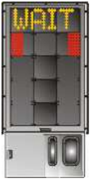
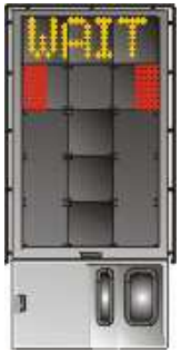
1.2.1 START-OF-DOCKING
The system is activated by pressing one of the aircraft type buttons on the operator panel. When the system has been activated, 'WAIT' will be displayed. |
|
|
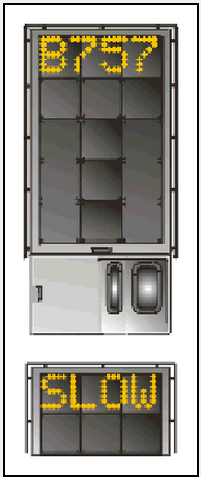
1.2.2 CAPTURE
The yellow scrolling arrows indicate that the system is activated and in capture mode, searching for an approaching aircraft. It shall be checked that the correct aircraft type is displayed. The lead-in line shall be followed.
|
|
|
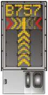
1.2.3 TRACKING
On successful capture of the aircraft, the yellow scrolling arrows are replaced by the yellow centre line indicator (Closing Rate Bar). The flashing red arrow indicates the direction the aircraft should turn. The vertical yellow arrow shows position in relation to the centre line. This indicator gives the correct position and azimuth guidance.
|
|
|
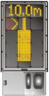
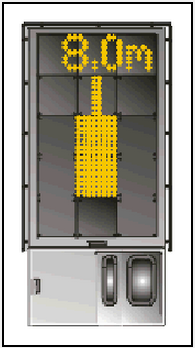
1.2.4 CLOSING RATE
Display of digital countdown starts when the aircraft is 20 meters from stop position.
|
|
|
1.2.5 ALIGNED TO CENTRE
The absence of any direction arrow indicates the aircraft is on the centre line.
|
|
|
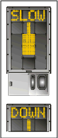
1.2.6 SLOW DOWN
If the aircraft is approaching faster than the accepted speed, the system will show 'SLOW DOWN' as a warning to the pilot.
|
|
|
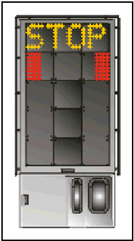
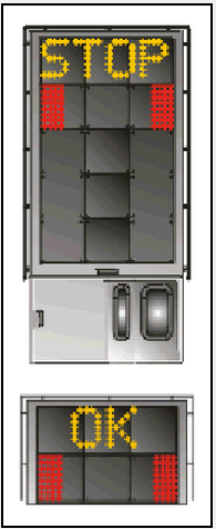
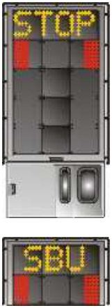
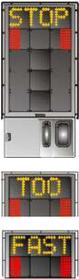
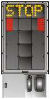
1.2.7 STOP-POSITION REACHED
When the correct stop-position is reached, the display will show 'STOP' and red lights will be lit.
|
|
|
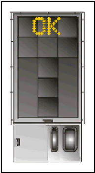
1.2.8 DOCKING COMPLETED
When the aircraft has parked, 'OK' will be displayed.
|
|
|
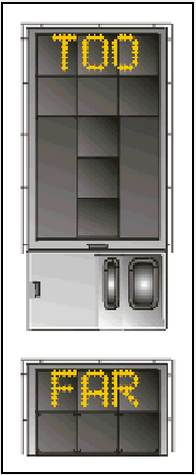
1.2.9 OVERSHOOT
If the aircraft has overshot the stop-position, 'TOO FAR' will be displayed.
|
|
|
1.2.10 STOP SHORT
If the aircraft is found standing still but has not reached the intended stop-position, the message 'STOP OK' will be shown after a while.
|
|
|
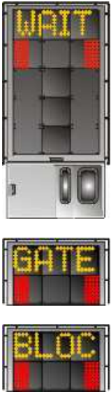
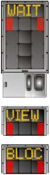
1.2.11 WAIT
If some object is blocking the view toward the approaching aircraft or the detected aircraft is lost during docking close to STOP, the display will show 'WAIT'.
|
|
|
1.2.12 SLOW
This display can be shown for two reasons:
|
|
|
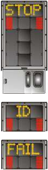
1.2.13 AIRCRAFT VERIFICATION FAILURE
During entry into the stand, the aircraft geometry is being checked. If, for any reason, aircraft verification is not made 12 meters before the stop-position, the display will first show 'WAIT' and make a second verification check. If this fails, 'STOP' and 'ID FAIL' will be displayed. The text will be alternating on the upper two rows of the display.
|
|
|
1.2.14 GATE BLOCKED
If an object is found blocking the view from the docking system to the planned stop position for the aircraft, the docking procedure will be halted with a 'WAIT' and 'GATE BLOC' message. The docking procedure will resume as soon as the blocking object has been removed.
|
|
|
1.2.15 VIEW BLOCKED
If the view towards the approaching aircraft is hindered, for instance by dirt on the window, the docking system will report a view blocked condition, i.e. ‘VIEW BLOC’. Once the system is able to see the aircraft through the dirt, the message will be replaced by closing rate bar.
|
|
|
1.2.16 SBU-STOP
Any unrecoverable error during the docking procedure will generate a SBU (Safety Back Up) condition. The display will show red stop-bar and 'STOP SBU' message.
|
|
|
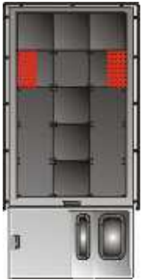
1.2.17 TOO FAST
If the aircraft approaches with a speed higher than the docking system can handle, the message 'STOP' (with red squares) and 'TOO FAST' will be displayed. The docking system will be re-started or the docking procedure completed by manual guidance.
|
|
|
1.2.18 EMERGENCY STOP
Pilots should stop the aircraft immediately when 'STOP' is displayed.
|
|
|
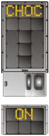
1.2.19 CHOCKS ON
'CHOC ON' will be displayed, when the ground staff has put the chocks in front of the nose wheel and pressed the "chocks on" button on the operator panel.
|
|
|
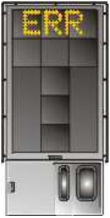
1.2.20 ERROR
If a system error occurs, the message 'ERR' will be displayed.
|
|
|
1.2.21 SYSTEM BREAKDOWN
In case of a severe system failure, the display will go black except for the red stop indicator. A manual backup procedure will be used for docking guidance.
|
|
|
1.2.22 POWER FAILURE
In case of a power failure, the display will be completely black. A manual backup procedure will be used for docking guidance.
|
|
OTBD AD 2.24 CHARTS RELATED TO AN AERODROME
|
AERODROME GROUND MOVEMENT CHART - ICAO

|
|
AIRCRAFT PARKING / DOCKING CHART - ICAO MAIN & WESTERN APRONS
|
|
AIRCRAFT PARKING / DOCKING CHART - ICAO EASTERN APRONS
|
|
AERODROME LIGHTING CHART
|
|
AERODROME OBSTACLE CHART - ICAO RWY 15/33 TYPE A
|
|
PRECISION APPROACH TERRAIN CHART - ICAO RWY 33
|
|
SID - ICAO RWY 15 BATHA 2S/SALWA 2S RNP CHART
|
|
SID - ICAO RWY 15 BATHA 2S/SALWA 2S RNP TABULAR
|
|
SID - ICAO RWY 15 ALSEM 2S/BUNDU 2S/NAMLA 2S/VAXIN 2S RNP CHART
|
|
SID - ICAO RWY 15 ALSEM 2S/BUNDU 2S/NAMLA 2S/VAXIN 2S RNP TABULAR
|
|
SID - ICAO RWY 15 ALVEN 2S/LUBET 1S/TULUB 1S RNP CHART
|
|
SID - ICAO RWY 15 ALVEN 2S/LUBET 1S/TULUB 1S RNP TABULAR
|
|
SID - ICAO RWY 15 PATOM 2S RNP CHART
|
|
SID - ICAO RWY 15 PATOM 2S RNP TABULAR
|
|
SID - ICAO RWY 33 ALVEN 2N/LUBET 1N/TULUB 1N RNP CHART
|
|
SID - ICAO RWY 33 ALVEN 2N/LUBET 1N/TULUB 1N RNP TABULAR
|
|
SID - ICAO RWY 33 ALSEM 2N/BUNDU 2N/NAMLA 2N/VAXIN 2N RNP CHART
|
|
SID - ICAO RWY 33 ALSEM 2N/BUNDU 2N/NAMLA 2N/VAXIN 2N RNP TABULAR
|
|
SID - ICAO RWY 33 BATHA 2N/SALWA 2N RNP CHART
|
|
SID - ICAO RWY 33 BATHA 2N/SALWA 2N RNP TABULAR
|
|
SID - ICAO RWY 33 PATOM 2N RNP CHART
|
|
SID - ICAO RWY 33 PATOM 2N RNP TABULAR
|
|
STAR - ICAO RWY 15 ALKAN 1F/RASDI 1F/VEDED 1F RNP CHART
|
|
STAR - ICAO RWY 15 ALKAN 1F/RASDI 1F/VEDED 1F RNP TABULAR
|
|
STAR - ICAO RWY 15 ALKAN 1F/RASDI 1F/VEDED 1F RNP TABULAR CONTINUED
|
|
STAR - ICAO RWY 15 DENSI 1F/DENSI 1K/MEKMA 1F/TOSNA 1F/ULIKA 1F RNP CHART
|
|
STAR - ICAO RWY 15 DENSI 1F/DENSI 1K/MEKMA 1F/TOSNA 1F/ULIKA 1F RNP TABULAR
|
|
STAR - ICAO RWY 33 ALKAN 1L/RASDI 1L/TOSNA 1J/VEDED 1L RNP CHART
|
|
STAR - ICAO RWY 33 ALKAN 1L/RASDI 1L/TOSNA 1J/VEDED 1L RNP TABULAR
|
|
STAR - ICAO RWY 33 ALKAN 1L/RASDI 1L/TOSNA 1J/VEDED 1L RNP TABULAR CONTINUED
|
|
STAR - ICAO RWY 33 DENSI 1L/DENSI 1J/MEKMA 1L/TOSNA 1L/ULIKA 1L RNP CHART
|
|
STAR - ICAO RWY 33 DENSI 1L/DENSI 1J/MEKMA 1L/TOSNA 1L/ULIKA 1L RNP TABULAR
|
|
IAC - ICAO RWY 15 ILS CHART
|
|
IAC - ICAO RWY 15 ILS TABULAR
|
|
IAC - ICAO RWY 15 RNP CHART
|
|
IAC - ICAO RWY 15 RNP TABULAR
|
|
IAC - ICAO RWY 33 ILS CHART
|
|
IAC - ICAO RWY 33 ILS TABULAR
|
|
IAC - ICAO RWY 33 RNP CHART
|
|
IAC - ICAO RWY 33 RNP TABULAR
|
|
IAC - ICAO NDB RWY 33 CHART
|
|
VISUAL APPROACH CHART - ICAO
|
|
HELICOPTER ROUTE CHART
|
|
BIRD CONCENTRATIONS
|
|
SID - ICAO RWY 15 BATHA 1S RNP
|
|
SID - ICAO RWY 15 ALSEM 1S / BUNDU 1S / NAMLA 1S / VAXIN 1S RNP
|
|
SID - ICAO RWY 15 ALVEN 1S / PATOM 1S RNP
|
|
SID - ICAO RWY 15 SALWA 1S RNP
|
|
SID - ICAO RWY 33 BATHA 1N RNP
|
|
SID - ICAO RWY 33 ALSEM 1N / BUNDU 1N / NAMLA 1N / VAXIN 1N RNP
|
|
SID - ICAO RWY 33 ALVEN 1N / PATOM 1N RNP
|
|
SID - ICAO RWY 33 SALWA 1N RNP
|
|
STAR - ICAO RWY 15 AFNAN 1A / BAYAN 1A / GINTO 1A RNP
|
|
STAR - ICAO RWY 33 AFNAN 1D / BAYAN 1D / GINTO 1D RNP
|
|
IAC - ICAO RWY 15 ILS
|
|
IAC - ICAO RWY 15 RNP
|
|
IAC - ICAO RWY 33 ILS
|
|
IAC - ICAO RWY 33 RNP
|
|
IAC - ICAO NDB RWY 33
|
|
VISUAL APPROACH CHART - ICAO
|
|
HELICOPTER ROUTE CHART
|
|
BIRD CONCENTRATIONS
|
OTBD AD 2.25 VISUAL SEGMENT SURFACE (VSS) PENETRATION
VSS is penetrated for the following Approaches of THR RWY 33.
| PROCEDURE | OCA / OCH (FT) | VSS PENETRATION | |||||||||
|---|---|---|---|---|---|---|---|---|---|---|---|
| OBST Description | OBST ELEV (FT) | Penetration (FT) | OBST Location | ||||||||
| A | B | C | D | E | LAT | LONG | Description | ||||
| OTBD RNP RWY 33 (LNAV/VNAV) | 390 / 363 | Streetlight | 110 | 17.51 | 251407.46N | 0513425.71E | 0.36NM before THR RWY 33, left of approach centreline. | ||||
| Streetlight | 110 | 9.83 | 251405.42N | 0513426.80E | 0.40NM before THR RWY 33, left of approach centreline. | ||||||
| Streetlight | 109 | 1.96 | 251403.39N | 0513427.88E | 0.44NM before THR RWY 33, left of approach centreline. | ||||||
| OTBD RNP RWY 33 (LNAV) | 420 / 393 | Streetlight | 110 | 17.51 | 251407.46N | 0513425.71E | 0.36NM before THR RWY 33, left of approach centreline. | ||||
| Streetlight | 110 | 9.83 | 251405.42N | 0513426.80E | 0.40NM before THR RWY 33, left of approach centreline. | ||||||
| Streetlight | 109 | 1.96 | 251403.39N | 0513427.88E | 0.44NM before THR RWY 33, left of approach centreline. | ||||||