


OTHH — HAMAD INTL
OTHH AD 2.1 AERODROME LOCATION INDICATOR AND NAME
OTHH - HAMAD INTL
OTHH AD 2.2 AERODROME GEOGRAPHICAL AND ADMINISTRATIVE DATA
| 1 | ARP coordinates and site at AD | 251628N 0513630E Adjacent to control Tower building |
| 2 | Direction and distance from (city) | 5.5 NM East from Doha City Centre |
| 3 | Elevation / Reference temperature | 13 FT / 39.3°C |
| 4 | Geoid undulation at AD ELEV PSN | -98 FT |
| 5 | MAG VAR / Annual change | 2.6°E 2025 / 0.003°W |
| 6 | Aerodrome operator | QATAR COMPANY FOR AIRPORTS OPERATION AND MANAGEMENT - MATAR |
| Address | Chief Operating Officer Hamad International Airport P.O. Box 24730 DOHA STATE OF QATAR | |
| Telephone | +974 4010 7715, +974 4010 3999 | |
| Telefax | +974 4010 1010 | |
| AFS | SITA: DOHAOXH | |
| coohiaoffice@hamadairport.com.qa | ||
| Website | www.dohahamadairport.com | |
| 7 | Type of traffic permitted (IFR/VFR) | IFR/VFR |
| 8 | Remarks | Airport Operations Control Centre Duty Manager (AOCC DM) 24/7: Tel: +974 4010 3999 |
OTHH AD 2.3 OPERATIONAL HOURS
| 1 | AD Operator | H24 |
| 2 | Customs and immigration | H24 |
| 3 | Health and sanitation | H24 |
| 4 | AIS Briefing Office | H24 |
| 5 | ATS Reporting Office (ARO) | H24 |
| 6 | MET Briefing Office | H24 |
| 7 | ATS | H24 |
| 8 | Fuelling | H24 |
| 9 | Handling | H24 |
| 10 | Security | H24 |
| 11 | De-icing | Not required due to local climate. |
| 12 | Remarks | Runway operations may be suspended if required for routine maintenance and/or operational reasons. Information will be available on ATIS, refer OTHH AD 2.18 ATS Communication Facilities for details. |
OTHH AD 2.4 HANDLING SERVICES AND FACILITIES
| 1 | Cargo-handling facilities | Available |
| 2 | Fuel/oil types | Fuel: Jet A1 Oil: NIL |
| 3 | Fuelling facilities / capacity | Fuel Hydrant System on Concourse A, B, C, D and E, Remote Stands G1, G2, G4, G5, G6, H1, H2, H4, H5 AND H6, Apron 3, Apron 6 including MARS configuration, Emiri Apron, Victor Apron including MARS configuration, Cargo Apron and Stand Q4. Code C Stands in MARS configuration and GA Apron, Stands G7, G8, G9, G10, H7, H8, H9, H10, Q1, Q2, Q3, Q20, Q21, Q40, Q41, Q50, Q51, Apron 4, Apron 5, Stands F12, F13, F14, F15 and F16 Bowsers only. |
| 4 | De-icing facilities | Not Available. |
| 5 | Hangar space for visiting aircraft | NIL |
| 6 | Repair facilities for visiting aircraft | Available upon request and appointment Qatar Airways Technical |
| 7 | Remarks | For Handling services. Contact QAS. See Item 9 of GEN 1.1 and 2.5 of GEN 1.2 |
OTHH AD 2.5 PASSENGER FACILITIES
| 1 | Hotels | Hotel accommodation available in the airport and in Doha City |
| 2 | Restaurants | H24 Airport restaurant in the terminal building |
| 3 | Transportation | Bus Services, Taxi and courtesy coaches to hotels |
| 4 | Medical Facilities | Airport's Medical Centre located at passenger terminal complex. Operated H24. Full medical facilities (Level 3 Hospital) are available in the City of Doha. Ambulance available at airport. |
| 5 | Bank and Post Office | Available at Airport Terminal building |
| 6 | Tourist Office | Available at Airport Terminal building |
| 7 | Remarks | NIL |
OTHH AD 2.6 RESCUE AND FIRE FIGHTING SERVICES
| 1 | AD category for fire fighting | CAT 10 |
| 2 | Rescue equipment | Rescue equipment: As per ICAO Annex 14 and QCAR - ADR - "Aerodrome Design, Operations and Licensing" |
| 3 | Capability for removal of disabled aircraft | The recovery equipment available at Hamad International Airport is able to assist in the recovery of aircraft up to and including A380. The disabled Aircraft Recovery Team shall be activated through the Qatar Airways OCC H24. Duty Manager Telephone number(s) +974 4018 4500 / +974 4018 4977 to activate the Disabled Aircraft Recovery Team. |
| 4 | Remarks | Total number of trained personnel 100+. Communications with aircraft on ground available on 121.600 MHz. |
OTHH AD 2.7 SEASONAL AVAILABILITY - CLEARING
| 1 | Types of clearing equipment | NIL |
| 2 | Clearance priorities | N/A |
| 3 | Remarks | Local climate precludes the requirement. Aerodrome is available in all seasons. |
OTHH AD 2.8 APRONS, TAXIWAYS AND CHECK LOCATIONS/POSITIONS DATA
| 1 | Designation, surface and strength of aprons | APRON 3: concrete, PCR 1471/R/C/W/T APRON 4: concrete, PCR 979/R/A/W/T APRON 5: concrete, PCR 1471/R/C/W/T APRON 6: concrete, PCR 1471/R/C/W/T CARGO: concrete, PCR 979/R/A/W/T CONCOURSE A: concrete, PCR 979/R/A/W/T CONCOURSE B: concrete, PCR 979/R/A/W/T CONCOURSE C: concrete, PCR 979/R/A/W/T CONCOURSE D: concrete, PCR 979/R/A/W/T CONCOURSE E: concrete, PCR 979/R/A/W/T EMIRI APRON: concrete, PCR 979/R/A/W/T GA APRON: concrete, PCR 1471/R/C/W/T ISOLATION PAD: concrete, PCR 979/R/A/W/T MAINTENANCE: concrete, PCR 979/R/A/W/T REMOTE TRANSFER G: concrete, PCR 979/R/A/W/T REMOTE TRANSFER H: concrete, PCR 979/R/A/W/T VICTOR APRON: concrete, PCR 979/R/A/W/T |
| 2 | Designation, width, surface and strength of taxiways | TWY A between TWY V and 85 M from RWY 34R CL: 30 M, concrete, PCR 979/R/A/W/T TWY A between 85 M from RWY 34R CL and RWY 34R CL: 30 M, asphalt, PCR 851/F/A/W/T TWY A1 between TWY C and 85 M from RWY 34R CL: 30 M, concrete, PCR 979/R/A/W/T TWY A1 between 85 M from RWY 34R CL and RWY 34R CL: 30 M, asphalt, PCR 851/F/A/W/T TWY A2 between RWY and TWY C: 30 M, asphalt, PCR 851/F/A/W/T TWY A2 between TWY C and TWY V: 30 M, concrete, PCR 979/R/A/W/T TWY A3: 30 M, asphalt, PCR 851/F/A/W/T TWY A4: 30 M, asphalt, PCR 851/F/A/W/T TWY A5: 30 M, asphalt, PCR 851/F/A/W/T TWY A6: 30 M, asphalt, PCR 851/F/A/W/T TWY A7: 30 M, asphalt, PCR 851/F/A/W/T TWY A8 between RWY and 59 M west of TWY B CL: 30 M, asphalt, PCR 851/F/A/W/T TWY A8 between 59 M west of TWY B CL and TWY F: 30 M, concrete, PCR 979/R/A/W/T TWY A9 between RWY and 59 M west of TWY B CL: 30 M, asphalt, PCR 851/F/A/W/T TWY A9 between 59 M west of TWY B CL and TWY F: 30 M, concrete, PCR 979/R/A/W/T TWY A10: 30 M, asphalt, PCR 851/F/A/W/T TWY A11: 30 M, asphalt, PCR 851/F/A/W/T TWY A12: 30 M, asphalt, PCR 851/F/A/W/T TWY B between TWY A and TWY A2: 25 M, concrete, PCR 979/R/A/W/T TWY B between TWY A2 and TWY A12: 25 M, asphalt, PCR 851/F/A/W/T TWY C between TWY A and TWY A8: 25 M, concrete, PCR 979/R/A/W/T TWY C between TWY Q and Stand 428W: 25 M, concrete, PCR 979/R/A/W/T TWY C between Stand 428W and TWY A12: 25 M, asphalt, PCR 851/F/A/W/T TWY D: 25 M, concrete, PCR 1471/R/C/W/T TWY E: 30 M, concrete, PCR 979/R/A/W/T TWY E1: 25 M, concrete, PCR 979/R/A/W/T TWY E2: 25 M, concrete, PCR 979/R/A/W/T TWY E3: 25 M, concrete, PCR 979/R/A/W/T TWY E4: 25 M, concrete, PCR 979/R/A/W/T TWY EL: 30 M, concrete, PCR 979/R/A/W/T TWY F: 25 M, concrete, PCR 979/R/A/W/T TWY G: 30 M, asphalt, PCR 851/F/A/W/T TWY H: 25 M, concrete, PCR 1471/R/C/W/T TWY J: 25 M, concrete, PCR 1471/R/C/W/T TWY K between TWY L and TWY G: 25 M, concrete, PCR 979/R/A/W/T TWY K between TWY G and TWY S: 25 M, asphalt, PCR 851/F/A/W/T TWY K between TWY S and TWY R: 25 M, concrete, PCR 979/R/A/W/T TWY K between TWY R and TWY L12: 25 M, asphalt, PCR 851/F/A/W/T TWY L between TWY W and 85 M from RWY 34L CL: 30 M, concrete, PCR 979/R/A/W/T TWY L between 85 M from RWY 34L CL and RWY 34L CL: 30 M, asphalt, PCR 851/F/A/W/T TWY L1 between TWY H and 85 M from RWY 34L CL: 30 M, concrete, PCR 979/R/A/W/T TWY L1 between 85 M from RWY 34L CL and RWY 34L CL: 30 M, asphalt, PCR 851/F/A/W/T TWY L2: 30 M, asphalt, PCR 851/F/A/W/T TWY L3: 30 M, asphalt, PCR 851/F/A/W/T TWY L4: 30 M, asphalt, PCR 851/F/A/W/T TWY L5: 30 M, asphalt, PCR 851/F/A/W/T TWY L6: 30 M, asphalt, PCR 851/F/A/W/T TWY L7: 30 M, asphalt, PCR 851/F/A/W/T TWY L8: 30 M, asphalt, PCR 851/F/A/W/T |
| 2 | TWY L9: 30 M, asphalt, PCR 851/F/A/W/T TWY L10 between RWY 16R/34L and TWY K: 30 M, asphalt, PCR 851/F/A/W/T TWY L10 between TWY K and TWY J: 25 M, concrete, PCR 979/R/A/W/T TWY L11 between RWY 16R/34L and TWY K: 30 M, asphalt, PCR 851/F/A/W/T TWY L11 between TWY K and TWY J: 25 M, concrete, PCR 979/R/A/W/T TWY L12 between RWY 16R/34L and TWY K: 30 M, asphalt, PCR 851/F/A/W/T TWY L12 between TWY K and TWY J: 25 M, concrete, PCR 979/R/A/W/T TWY M: 25 M, concrete, PCR 979/R/A/W/T TWY M1: 25 M, concrete, PCR 979/R/A/W/T TWY M2: 25 M, concrete, PCR 979/R/A/W/T TWY M3: 25 M, concrete, PCR 979/R/A/W/T TWY M4: 25 M, concrete, PCR 979/R/A/W/T TWY M5 between TWY M and 80 M from edge of RWY 16R: 25 M, concrete, PCR 979/R/A/W/T TWY M5 between 80 M from edge of RWY 16R and RWY 16R edge: 25 M, asphalt, PCR 851/F/A/W/T TWY M6 between TWY M and 67 M from edge of RWY 34L: 25 M, concrete, PCR 979/R/A/W/T TWY M6 between 67 M from edge of RWY 34L and RWY 34L edge: 25 M, asphalt, PCR 851/F/A/W/T TWY M7 between TWY M and 73 M from edge of RWY 16R: 25 M, concrete, PCR 979/R/A/W/T TWY M7 between 73 M from edge of RWY 16R and RWY 16R edge: 25 M, asphalt, PCR 851/F/A/W/T TWY M8 between TWY M and 75 M from edge of RWY 34L: 25 M, concrete, PCR 979/R/A/W/T TWY M8 between 75 M from edge of RWY 34L and RWY 34L edge: 25 M, asphalt, PCR 851/F/A/W/T TWY M9 between TWY M and 75 M from edge of RWY 16R: 25 M, concrete, PCR 979/R/A/W/T TWY M9 between 75 M from edge of RWY 16R and RWY 16R edge: 25 M, asphalt, PCR 851/F/A/W/T TWY M10 between TWY M and 77 M from edge of RWY 34L: 25 M, concrete, PCR 979/R/A/W/T TWY M10 between 77 M from edge of RWY 34L and RWY 34L edge: 25 M, asphalt, PCR 851/F/A/W/T TWY M11: 25 M, concrete, PCR 979/R/A/W/T TWY M12: 25 M, concrete, PCR 979/R/A/W/T TWY M13: 25 M, concrete, PCR 979/R/A/W/T TWY M14: 25 M, concrete, PCR 979/R/A/W/T TWY N: 25 M, concrete, PCR 1471/R/C/W/T TWY P: 25 M, concrete, PCR 979/R/A/W/T TWY P1: 25 M, concrete, PCR 979/R/A/W/T TWY P2: 25 M, concrete, PCR 979/R/A/W/T TWY P3: 25 M, concrete, PCR 979/R/A/W/T TWY P4: 25 M, concrete, PCR 979/R/A/W/T TWY P5: 25 M, concrete, PCR 979/R/A/W/T TWY P6: 25 M, concrete, PCR 979/R/A/W/T TWY P7: 25 M, concrete, PCR 979/R/A/W/T TWY P8: 25 M, concrete, PCR 979/R/A/W/T TWY P9: 25 M, concrete, PCR 979/R/A/W/T TWY P10: 25 M, concrete, PCR 979/R/A/W/T TWY P11: 25 M, concrete, PCR 979/R/A/W/T TWY P12: 25 M, concrete, PCR 979/R/A/W/T TWY P13: 25 M, concrete, PCR 979/R/A/W/T TWY P14: 25 M, concrete, PCR 979/R/A/W/T TWY Q between TWY B CL and 60 M from TWY B CL: 25 M, asphalt, PCR 851/F/A/W/T TWY Q between 60 M from TWY B CL and 193 M from TWY B CL: 25 M, concrete, PCR 979/R/A/W/T TWY Q between 193 M from TWY B CL and TWY Q2: 25 M, asphalt, PCR 851/F/A/W/T TWY Q1: 25 M, asphalt, PCR 851/F/A/W/T TWY Q2: 25 M, asphalt, PCR 851/F/A/W/T TWY R: 25 M, concrete, PCR 1471/R/C/W/T TWY R1 between TWY R2 and 32 M from RWY 16R/34L edge: 25 M, concrete, PCR 979/R/A/W/T TWY R1 between 32 M from edge of RWY 16R/34L and RWY 16R/34L edge: 25 M, asphalt, PCR 851/F/A/W/T TWY R2: 25 M, concrete, PCR 979/R/A/W/T TWY S: 25 M, concrete, PCR 1471/R/C/W/T TWY S1: 25 M, concrete, PCR 979/R/A/W/T TWY S2: 25 M, concrete, PCR 979/R/A/W/T TWY S3: 25 M, concrete, PCR 979/R/A/W/T TWY S4: 25 M, concrete, PCR 979/R/A/W/T TWY T: 40 M, asphalt, PCR 851/F/A/W/T TWY T1: 25 M, concrete, PCR 979/R/A/W/T TWY T2: 25 M, concrete, PCR 1255/R/B/W/T TWY T3: 25 M, concrete, PCR 979/R/A/W/T TWY T4: 25 M, concrete, PCR 979/R/A/W/T TWY T5: 25 M, concrete, PCR 979/R/A/W/T TWY T6: 25 M, concrete, PCR 979/R/A/W/T TWY T7: 25 M, concrete, PCR 979/R/A/W/T TWY T8: 25 M, concrete, PCR 979/R/A/W/T TWY T9: 25 M, concrete, PCR 979/R/A/W/T TWY V: 25 M, concrete, PCR 979/R/A/W/T TWY W: 30 M, concrete, PCR 1471/R/C/W/T | |
| 2 | TWY W1: 25 M, concrete, PCR 979/R/A/W/T TWY W2: 25 M, concrete, PCR 979/R/A/W/T TWY W3: 25 M, concrete, PCR 979/R/A/W/T TWY W4: 25 M, concrete, PCR 979/R/A/W/T TWY WL: 30 M, concrete, PCR 979/R/A/W/T TWY Y: 30 M, concrete, PCR 1471/R/C/W/T | |
| 3 | Altimeter checkpoint location and elevation | All aircraft stands: 17 FT |
| 4 | VOR checkpoints | NIL |
| 5 | INS checkpoints | See APDC.01 AIRCRAFT PARKING / DOCKING CHART - ICAO |
| 6 | Remarks | Code F aircraft operations are permitted on all taxiways except following taxiways: TWY E (BTN TWY D and Stand B2 - Max up to Code E) TWY M1 and TWY M12 (Max up to Code E except aircraft types with four engines (e.g.: B747 series and A340 series) TWY N (Max up to Code E) TWY W (BTN TWY H and Stand A4 – Max up to Code E) TWY Y (Max up to Code C) |
OTHH AD 2.9 SURFACE MOVEMENT GUIDANCE AND CONTROL SYSTEM AND MARKINGS
| 1 | Use of aircraft stand ID signs, TWY guide lines and visual docking/parking guidance system at aircraft stands | Mandatory signs at all intersections of TWYs and RWYs at all holding positions. Taxi information and location signs at all TWYs. Aircraft stand ID signs provided on all stands, except Apron 4 and MARS stands. VDGS installed and operational on all stands except for MARS stands, on APRON 4 stands, stands F12, F13, F14, F15, F16, G7, G8, G9, G10, H7, H8, H9, H10, 551 to 564. Stands not equipped with VDGS have marked centre lines and shall be marshalled. For information on Visual Docking Guidance System (VDGS); For stand A1 to A11, stand B1 to B10, stand C1 to C13, Apron 3, Apron 6, stand 118 to 126, stand 217 to 226, stand V6 to V12 refer: AD 2.23 ADDITIONAL INFORMATION - 1.4 Stand docking procedures For all other stands refer: AD 2.23 ADDITIONAL INFORMATION - 1.3 Stand docking procedures |
| 2 | RWY and TWY markings and lights | RWY: Designation, THR, TDZ, CL, Edge, RWY end. See AD 2.14 APPROACH AND RUNWAY LIGHTING and AD 2.15 OTHER LIGHTING AND SECONDARY POWER SUPPLY for additional information on lighting. TWY: Edge marking, CL, Holding Positions at all TWY / RWY intersections. Mandatory Taxiway Reporting Points are provided at some Intermediate Holding Positions, and marked by five - letter designations on ground in white on red background. See AD 2.20 section 3 TAXIWAY UTILIZATION AND LIMITATIONS. |
| 3 | Stop bars and RWY guard lights | Stop bars at all RWY entrances and where appropriate. RWY guard lights provided at all RWY holding positions where appropriate. |
| 4 | Other RWY protection measures | NIL |
| 5 | Remarks | NIL |
OTHH AD 2.10 AERODROME OBSTACLES
1 Obstacles in Area 2
2 Obstacles in Area 3
OTHH AD 2.11 METEOROLOGICAL INFORMATION PROVIDED
| 1 | Associated MET Office | Forecast and Analysis Office, Qatar Met Dept, Doha International Airport. |
| 2 | Hours of service | H24 |
| MET Office outside hours | NIL | |
| 3 | Office responsible for TAF preparation | Forecast and Analysis Office, Qatar Met Dept, Doha International Airport. |
| Periods of validity | H30 (prepared 6 hourly). | |
| 4 | Trend forecast | TREND |
| Interval of issuance | ½ HR | |
| 5 | Briefing/consultation provided | Issue of forecast folders, Personal consultations, self briefings, telephone consultation with duty forecaster. |
| 6 | Flight documentation | Charts, abbreviated plain language text. |
| Language(s) used | English | |
| 7 | Charts and other information available for briefing or consultation | S, U25, P25' (other levels on request), T, SWH (East & West), SWM, TB (Gulf sector winds). |
| 8 | Supplementary equipment available for providing information | Fax, e-mail, IVR (Interactive Voice Response) for general information. |
| 9 | ATS units provided with information | HAMAD TOWER, DOHA APPROACH |
| 10 | Additional information (limitation of service, etc.) | NIL |
OTHH AD 2.12 RUNWAY PHYSICAL CHARACTERISTICS
| Designations RWY NR | TRUE BRG | Dimensions of RWY (M) | Strength (PCR) and surface of RWY and SWY | THR coordinates, RWY end coordinates, THR geoid undulation | THR elevation and highest elevation of TDZ of precision APP RWY |
|---|---|---|---|---|---|
| 1 | 2 | 3 | 4 | 5 | 6 |
| 16L | 158.17° | 4850 x 60 | 851/F/A/W/T asphalt | 251745.97N 0513631.96E 251519.65N 0513736.41E -98.32 FT | THR 13.21 FT TDZ 13.39 FT |
| 34R | 338.18° | 4850 x 60 | 851/F/A/W/T asphalt | 251519.65N 0513736.41E 251745.97N 0513631.96E -98.57 FT | THR 13.13 FT TDZ 13.39 FT |
| 16R | 158.16° | 4250 x 60 | 851/F/A/W/T asphalt | 251727.52N 0513523.07E 251519.32N 0513619.56E -98.27 FT | THR 13.13 FT TDZ 13.50 FT |
| 34L | 338.17° | 4250 x 60 | 851/F/A/W/T asphalt | 251519.32N 0513619.56E 251727.52N 0513523.07E -98.49 FT | THR 13.22 FT TDZ 13.47 FT |
| Designations RWY NR | Slope of RWY - SWY | SWY dimensions (M) | CWY dimensions (M) | Strip dimensions (M) | RESA dimensions (M) | |
|---|---|---|---|---|---|---|
| RWY | SWY | |||||
| 1 | 7 | 8 | 9 | 10 | 11 | |
| 16L | 0 | NIL | NIL | NIL | 4970 x 300 | 240 x 120 |
| 34R | 0 | NIL | NIL | NIL | 4970 x 300 | 240 x 120 |
| 16R | 0 | NIL | NIL | NIL | 4370 x 300 | 240 x 120 |
| 34L | 0 | NIL | NIL | NIL | 4370 x 300 | 240 x 120 |
| Designations RWY NR | Location and Description of Arresting System | OFZ | Remarks |
|---|---|---|---|
| 1 | 12 | 13 | 14 |
| 16L | NIL | Yes | Non-load bearing Runway shoulders - 7.5 M each side |
| 34R | NIL | Yes | Non-load bearing Runway shoulders - 7.5 M each side |
| 16R | NIL | Yes | Non-load bearing Runway shoulders - 7.5 M each side |
| 34L | NIL | Yes | Non-load bearing Runway shoulders - 7.5 M each side |
OTHH AD 2.13 DECLARED DISTANCES
| RWY Designator | From | TORA (M) | TODA (M) | ASDA (M) | LDA (M) | Remarks |
|---|---|---|---|---|---|---|
| 1 | 2 | 3 | 4 | 5 | 6 | 7 |
| 16L | THR | 4850 | 4850 | 4850 | 4850 | NIL |
| TWY A11 | 4730 | 4730 | 4730 | Not Applicable | NIL | |
| TWY A10 | 4082 | 4082 | 4082 | Not Applicable | NIL | |
| TWY A6 | 2497 | 2497 | 2497 | Not Applicable | NIL | |
| 34R | THR | 4850 | 4850 | 4850 | 4850 | NIL |
| TWY A1 | 4730 | 4730 | 4730 | Not Applicable | NIL | |
| TWY A2 | 4266 | 4266 | 4266 | Not Applicable | NIL | |
| TWY A3 | 3077 | 3077 | 3077 | Not Applicable | NIL | |
| TWY A6 | 2386 | 2386 | 2386 | Not Applicable | NIL | |
| 16R | THR | 4250 | 4250 | 4250 | 4250 | NIL |
| TWY M13 | 4212 | 4212 | 4212 | Not Applicable | NIL | |
| TWY L11 | 4130 | 4130 | 4130 | Not Applicable | NIL | |
| TWY M12 | 3817 | 3817 | 3817 | Not Applicable | NIL | |
| TWY L10 | 3614 | 3614 | 3614 | Not Applicable | NIL | |
| TWY M11 | 3613 | 3613 | 3613 | Not Applicable | NIL | |
| TWY L7 | 2348 | 2348 | 2348 | Not Applicable | NIL | |
| TWY R | 1704 | 1704 | 1704 | Not Applicable | NIL | |
| TWY R1 | 1704 | 1704 | 1704 | Not Applicable | NIL | |
| TWY S | 1604 | 1604 | 1604 | Not Applicable | NIL | |
| TWY S1 | 1604 | 1604 | 1604 | Not Applicable | NIL | |
| 34L | THR | 4250 | 4250 | 4250 | 4250 | NIL |
| TWY M2 | 4195 | 4195 | 4195 | Not Applicable | NIL | |
| TWY L1 | 4122 | 4122 | 4122 | Not Applicable | NIL | |
| TWY M3 | 3785 | 3785 | 3785 | Not Applicable | NIL | |
| TWY L2 | 3646 | 3646 | 3646 | Not Applicable | NIL | |
| TWY M4 | 3646 | 3646 | 3646 | Not Applicable | NIL | |
| TWY S | 2672 | 2672 | 2672 | Not Applicable | NIL | |
| TWY S1 | 2672 | 2672 | 2672 | Not Applicable | NIL | |
| TWY R | 2572 | 2572 | 2572 | Not Applicable | NIL | |
| TWY R1 | 2572 | 2572 | 2572 | Not Applicable | NIL | |
| TWY L7 | 1935 | 1935 | 1935 | Not Applicable | NIL |
| Note: Intersection departures are allowed subject to the following: a. Initiated by pilot and approved by ATC, subject to traffic. b. ATC is able to keep aircraft visual at all times |
OTHH AD 2.14 APPROACH AND RUNWAY LIGHTING
| RWY Designator | APCH LGT type, LEN, INTST | THR LGT, colour, WBAR | VASIS (MEHT) PAPI | TDZ LGT LEN | RWY Centre Line LGT Length, spacing, colour, INTST |
|---|---|---|---|---|---|
| 1 | 2 | 3 | 4 | 5 | 6 |
| 16L | CAT III 900 M LIH | LIH, GREEN supplemented by WBAR | PAPI 3° (16.2 M) | 900 M | Length: 4 850 M Spacing: 15 M Colour: fm 0 M to last 900 M White last 900 M to last 300 M Red / White last 300 M Red INTST: LIH |
| 34R | CAT III 900 M LIH | LIH, GREEN supplemented by WBAR | PAPI 3° (19.902 M) | 900 M | Length: 4 850 M Spacing: 15 M Colour: fm 0 M to last 900 M White last 900 M to last 300 M Red / White last 300 M Red INTST: LIH |
| 16R | CAT III 900 M LIH | LIH, GREEN supplemented by WBAR | PAPI 3° (19.903 M) | 900 M | Length: 4 250 M Spacing: 15 M Colour: fm 0 M to last 900 M White last 900 M to last 300 M Red / White last 300 M Red INTST: LIH |
| 34L | CAT III 900 M LIH | LIH, GREEN supplemented by WBAR | PAPI 3° (19.899 M) | 900 M | Length: 4 250 M Spacing: 15 M Colour: fm 0 M to last 900 M White last 900 M to last 300 M Red / White last 300 M Red INTST: LIH |
| RWY Designator | RWY edge LGT LEN, spacing, colour, INTST | RWY End LGT colour, WBAR | SWY LGT LEN, colour | Remarks |
|---|---|---|---|---|
| 1 | 7 | 8 | 9 | 10 |
| 16L | Length: 4 850 M Spacing: 60 M Colour: fm 0 M to last 600 M White last 600 M Yellow INTST: LIH | RED, NIL | NIL | NIL |
| 34R | Length: 4 850 M Spacing: 60 M Colour: fm 0 M to last 600 M White last 600 M Yellow INTST: LIH | RED, NIL | NIL | NIL |
| 16R | Length: 4 250 M Spacing: 60 M Colour: fm 0 M to last 600 M White last 600 M Yellow INTST: LIH | RED, NIL | NIL | NIL |
| 34L | Length: 4 250 M Spacing: 60 M Colour: fm 0 M to last 600 M White last 600 M Yellow INTST: LIH | RED, NIL | NIL | NIL |
OTHH AD 2.15 OTHER LIGHTING AND SECONDARY POWER SUPPLY
| 1 | ABN / IBN location, characteristics and hours of operation | ABN: NIL IBN: NIL |
| 2 | LDI location and LGT | LDI: NIL |
| Anemometer location and LGT | Anemometer: 16L - 251736.4560N 0513640.7313E 34R - 251532.1162N 0513735.5462E 16R - 251715.2675N 0513524.0348E 34L - 251530.2198N 0513609.9122E Automated Weather Observing System (AWOS). WS425 Ultrasonic wind Sensor | |
| 3 | TWY edge and centre line lighting | Rapid Exit Taxiway Indicator Lights (RETIL) marked and lit when required. RETIL lead-off lights are alternate green/amber indicating within ILS sensitive area. Taxiway centreline lights are green, except when within ILS sensitive area, where taxiway centre line lights are alternate green/amber. |
| 4 | Secondary power supply/switch-over time | Available via UPS immediate power. Standby generator also available. Switch-over time of less than 1 second. |
| 5 | Remarks | NIL |
OTHH AD 2.16 HELICOPTER LANDING AREA
| 1 | Coordinates TLOF or THR of FATO Geoid undulation | NIL |
| 2 | TLOF and/or FATO elevation M/FT | NIL |
| 3 | TLOF and FATO area dimensions, surface, strength, marking | NIL |
| 4 | True BRG of FATO | NIL |
| 5 | Declared distance available | NIL |
| 6 | APP and FATO lighting | NIL |
| 7 | Remarks | NIL |
OTHH AD 2.17 ATS AIRSPACE
| 1 | Designation and lateral limits | DOHA CTR Lateral limits are available in the AIP Data set, Feature ID: 8d22fe52-2ea1-4e50-9d95-28990073b667 Standardised presentation of the airspace lateral limits: 253407N 0513740E - 253023N 0513919E then clockwise 20NM arc centred on 251020N 0513838E to 252814N 0514835E - 251255N 0515519E then clockwise 20NM arc centred on 251939N 0513432E to 250143N 0512438E - 245951N 0511930E - 250205N 0511831E then clockwise 5NM arc centred on 250706N 0511846E to 251032N 0511446E - 251510N 0511243E - 251703N 0511751E then clockwise 20NM arc centred on 251020N 0513838E to 252425N 0512254E - 252808N 0512115E then clockwise 20NM arc centred on 251404N 0513659E to 253407N 0513740E. |
| 2 | Vertical limits | SFC to 2500 FT |
| 3 | Airspace classification | Class D |
| 4 | ATS unit call sign Language(s) | HAMAD TOWER EAST EN HAMAD TOWER WEST EN |
| 5 | Transition altitude | 13000 FT |
| 6 | Hour of applicability | H24 |
| 7 | Remarks | NIL |
OTHH AD 2.18 ATS COMMUNICATION FACILITIES
| Service designation | Call sign | Channel(s) | SATVOICE number(s) | Logon address | Hours of operation | Remarks |
|---|---|---|---|---|---|---|
| 1 | 2 | 3 | 4 | 5 | 6 | 7 |
| APP | DOHA APPROACH EAST | 124.775 MHz As directed by ATC | N/A | N/A | H24 | Primary |
| 120.600 MHz As directed by ATC | N/A | N/A | Secondary | |||
| DOHA APPROACH WEST | 119.725 MHz | N/A | N/A | H24 | Primary | |
| 125.125 MHz | N/A | N/A | Secondary | |||
| DOHA DIRECTOR | 124.050 MHz As directed by ATC | N/A | N/A | H24 | Primary | |
| 121.775 MHz As directed by ATC | N/A | N/A | Secondary | |||
| DOHA DIRECTOR EAST | 119.400 MHz | N/A | N/A | H24 | Primary | |
| 121.125 MHz | N/A | N/A | Secondary | |||
| DOHA DIRECTOR WEST | 123.875 MHz As directed by ATC | N/A | N/A | H24 | Primary | |
| 119.225 MHz As directed by ATC | N/A | N/A | Secondary | |||
| DOHA RADAR NORTH | 121.100 MHz | N/A | N/A | H24 | Primary | |
| 121.625 MHz | N/A | N/A | Secondary | |||
| DOHA RADAR SOUTH | 120.675 MHz As directed by ATC | N/A | N/A | H24 | Primary | |
| 119.150 MHz As directed by ATC | N/A | N/A | Secondary | |||
| - | 121.500 MHz | N/A | N/A | H24 | Emergency | |
| 243.000 MHz | N/A | N/A | Emergency | |||
| TWR | HAMAD CLEARANCE DELIVERY | 120.875 MHz | N/A | N/A | H24 | (See Note 2) |
| HAMAD TOWER EAST | 118.525 MHz | N/A | N/A | H24 | (See Note 1) Primary | |
| 118.225 MHz | N/A | N/A | Secondary | |||
| HAMAD TOWER WEST | 118.025 MHz | N/A | N/A | H24 | (See Note 1) Primary | |
| 118.225 MHz | N/A | N/A | Secondary | |||
| - | 121.500 MHz | N/A | N/A | H24 | Emergency | |
| 243.000 MHz | N/A | N/A | Emergency | |||
| GMC | HAMAD GROUND | 121.675 MHz As directed by ATC | N/A | N/A | H24 | Secondary |
| HAMAD GROUND CENTRAL | 118.650 MHz | N/A | N/A | H24 | ||
| HAMAD GROUND EAST | 120.225 MHz | N/A | N/A | H24 | ||
| HAMAD GROUND OVERFLOW | 118.075 MHz As directed by ATC | N/A | N/A | H24 | ||
| HAMAD GROUND PLANNER | 119.075 MHz As directed by ATC | N/A | N/A | H24 | ||
| HAMAD GROUND WEST | 118.575 MHz | N/A | N/A | H24 | ||
| ATIS DEP | HAMAD DEPARTURE INFORMATION | 126.850 MHz | N/A | DOHATYA | H24 | Data Link Service available. ATIS broadcast can also be obtained via Hotline: +974 4470 5312 |
| ATIS ARR | HAMAD ARRIVAL INFORMATION | 126.825 MHz | N/A | N/A | H24 | Data Link service available. ATIS broadcast can also be obtained via hotline: +974 4470 5310 |
| DCL | N/A | N/A | N/A | DOHDCYA | H24 | Data Link Service for departure clearance (See Note 2) |
| CPDLC | DOHA RADAR | N/A | N/A | N/A | H24 | SITA access address: DOHFAYA |
Note 1: All departing aircraft should remain on Tower frequency after departure and report passing 1000 FT. Departures from RWY 34L/16R should expect to be transferred to Doha Approach West on (119.725 MHz) and departures from RWY 34R/16L should expect to be transferred to Doha Approach East on (124.775 MHz). Note 2: Departure clearance via Data Link (DCL) and Departure clearances by voice on Hamad Clearance Delivery on 120.875 MHz may be requested by aircrew up to 25 minutes prior to EOBT. Requests for RWY in use should be avoided. Aircrews should as far as practicable only contact Clearance Delivery when requesting departure clearance. |
OTHH AD 2.19 RADIO NAVIGATION AND LANDING AIDS
| Type of aids, MAG VAR, Type of supported OPS for ILS/MLS/GLS, basic GNSS and SBAS, Classification for ILS, Facility Classification and approach facility designation(s) for GBAS, VOR/ILS/MLS station declination | IDENT | Frequency, Channel number, Service provider | Hours of operation | Position of transmitting antenna coordinates | ELEV of DME transmitting antenna, GBAS reference point ELEV/ellipsoid HGT, SBAS LTP/FTP ellipsoid HGT | Service volume radius from the GBAS reference point | Remarks | |
|---|---|---|---|---|---|---|---|---|
| 1 | 2 | 3 | 4 | 5 | 6 | 7 | 8 | |
| DVOR/DME (2.6°E 2025) | DOH | 114.400 MHZ CH 91X | H24 | 251459.7N 0513634.8E | 0 FT | NIL | NIL | |
| ILS 16L (CAT III) (2.6°E 2025) III/E/4 | ||||||||
| LOC 16L | IDE | 108.700 MHZ | H24 | 251510.3N 0513740.5E | NIL | Distance from threshold 16L 5158.71M | ||
| GP 16L | 330.500 MHZ | H24 | 251738.2N 0513640.4E | NIL | 3° ILS RDH 55 FT | |||
| DME 16L | IDE | CH 24X | H24 | 251738.2N 0513640.4E | 30 FT | NIL | Co-located with GP, DIST zero TDZ | |
| ILS 16R (CAT III) (2.6°E 2025) III/E/4 | ||||||||
| LOC 16R | QAT | 108.100 MHZ | H24 | 251510.0N 0513623.7E | NIL | Distance from threshold 16R 4559.70M | ||
| GP 16R | 334.700 MHZ | H24 | 251716.6N 0513522.9E | NIL | 3° ILS RDH 53 FT | |||
| DME 16R | QAT | CH 18X | H24 | 251716.6N 0513522.9E | 30 FT | NIL | Co-located with GP, DIST zero TDZ | |
| ILS 34L (CAT III) (2.6°E 2025) III/E/4 | ||||||||
| LOC 34L | HJJ | 111.900 MHZ | H24 | 251736.9N 0513518.9E | NIL | Distance from threshold 34L 4562.47 M | ||
| GP 34L | 331.100 MHZ | H24 | 251528.7N 0513610.4E | NIL | 3° ILS RDH 53 FT | |||
| DME 34L | HJJ | CH 56X | H24 | 251528.7N 0513610.3E | 30 FT | NIL | Co-located with GP, DIST zero TDZ | |
| ILS 34R (CAT III) (2.6°E 2025) III/E/4 | ||||||||
| LOC 34R | AZM | 110.100 MHZ | H24 | 251755.5N 0513627.8E | NIL | Distance from threshold 34R 5165.49 M | ||
| GP 34R | 34R | 334.400 MHZ | H24 | 251530.6N 0513736.6E | NIL | 3° ILS RDH 53FT | ||
| DME 34R | AZM | CH 38X | H24 | 251530.6N 0513736.6E | 30 FT | NIL | Co-located with GP, DIST zero TDZ | |
OTHH AD 2.20 LOCAL AERODROME REGULATIONS
1 Airport regulations
safetyreports@hamadairport.com.qa
2 Runway utilisation AND LIMITATIONS
RWY 16R - L8, L5, L3, M9, M7, M5
RWY 34L - L4, L6, L9, M6, M8, M10
RWY 16L - A8, A7, A3
RWY 34R - A4, A5, A9
| Runway ID | Standard Runway Exit | Distance to turnoff* (m) |
|---|---|---|
| 16L | A7 | 1895 |
| 34R | A5 | 2006 |
| 16R | M7/L5 | 1971 |
| 34L | M8/L6 | 1841 |
| *Distance from threshold to turn off intersection | ||
| Note: Pilots should anticipate being issued the above RET’s | ||
| Design Speed | Radius | Exit Angle | Straight Distance on RET | |
|---|---|---|---|---|
| 50 Kt | 550 m | 29° | A3, A4, A5, A7, A8, A9 (16L / 34R) | 270 m |
| L3, L4, L5, L6, L8, L9 (16R / 34L) | 270 m | |||
| M5, M6, M7, M8, M9, M10 (16R / 34L) | 300 m | |||
- If vacating runway 16L, continue via taxiway A6 and hold short of C.
- If vacating runway 34R, continue via taxiway A6 and hold short of C.
- If vacating runway 16R, continue via taxiway K/M southbound.
- If vacating runway 16R and parking stand is planned on Apron 5, expect a northbound turn onto taxiway K.
- If vacating runway 34L, continue via taxiway K/M Southbound. If parking stand is planned North of the L6, expect instructions to continue Northbound on taxiway K.
- High Intensity Runway Operations for departing aircraft are in force 24 hours.
- All checks should be completed when reaching the assigned holding point.
- a. Line-up without delay when cleared by ATC.
- b. React promptly to take-off clearance.
- Intersection departures are encouraged to facilitate sequencing. Whenever possible, advise ATC if able to depart from the following intersection:
| Runway ID | Intersection | TORA (m) |
|---|---|---|
| 16L | A10 | 4082 |
| 34R | A2 | 4266 |
| 16R | L10 / M11 | 3614 |
| M12 | 3817 | |
| 34L | L2 / M 4 | 3646 |
| M3 | 3785 |
3 TAXIWAY UTILIZATION AND LIMITATIONS
4 AIRCRAFT PARKING STAND UTILIZATION AND LIMITATIONS
5 AIRPORT COLLABORATIVE DECISION MAKING (ACDM)
- A-CDM platform.
- Turnaround Coordinator.
- Parking stands equipped with VDGS.
- A-CDM platform at 30 minutes before TOBT.
- Turnaround Coordinator.
- Parking stands equipped with VDGS shall display TSAT.
Note: Flight deck crew shall not contact ATC for start-up request earlier than TSAT -2 minutes or later than TSAT +2 minutes.
- At TSAT +/- 2 minutes:
- Flight deck crew to call the appropriate ATC frequency, allocated during en-route clearance, to request start and push-back or start and taxi.
- Flight deck crew shall continue monitoring the ATC frequency.
- ATC will advise ATC-related changes to TSAT via frequency (if required).
- Aircraft are supposed to push-back at TSAT +/- 2 minutes.
- At TSAT + 5 minutes:
- If the pushback cannot be executed by TSAT + 5 minutes due to any reason (and the crew requested and received startup clearance from ATC within the TSAT +/- 2 minutes window), it is the flight deck crew’s responsibility to advise the ground handler and its airline representatives to update TOBT accordingly for a new TSAT.
- The flight deck crew may be required to coordinate with ATC for new clearances (start-up approval and/or en-route clearance if required) based on the new TSAT.
Note: Flight deck crew shall not contact ATC or report ready for start-up request prior TSAT. Unless start-up on parking stand is required, ref 5.3.5.
- If an ACFT requires to start engine/s while on parking stand (i.e due APU INOP), flight deck crew shall request engine start on stand at a time that ensures TSAT is met (i.e TSAT -5 minutes.)
- Pushback request (after engine start on stand) shall be made at TSAT -/+ 2 minutes.
- Ref 5.3.4 item 2, if at TSAT +5 minutes pushback cannot be executed.
6 Parking area for helicopters
(To be developed).
7 SCHOOL AND TRAINING FLIGHTS — TECHNICAL TEST FLIGHTS — USE OF RUNWAYS
7.1.1 Permissions shall be requested through:
| Tel: | +974 44705999 / +974 33337087 |
| E-mail: | twr.ops@caa.gov.qa |
7.2.1 VFR touch and go can be conducted at OTHH with prior approval of ATC (for additional information refer AD 2.3 OPERATIONAL HOURS ).
7.2.2 After touch and go, ACFT can expect a turn to the West unless otherwise instructed by ATC.
7.2.3 It is the pilot's responsibility to remain clear of restricted areas.
7.2.4 The VFR downwind for OTHH Western and Eastern RWY is 1000 FT along the Ras Abu Aboud Road.
8 Removal of disabled aircraft from runways
OTHH AD 2.21 NOISE ABATEMENT PROCEDURES
NIL
OTHH AD 2.22 FLIGHT PROCEDURES
1 Special procedures applicable to ILS category II / III operations
- OTHH: RWY 16L, CAT II or CAT III
- OTHH: RWY 34R, CAT II or CAT III
- OTHH: RWY 16R, CAT II or CAT III
- OTHH: RWY 34L, CAT II or CAT III
1.4 Authorization
| Post: | President Civil Aviation Authority P.O. Box 3000 Doha State of Qatar |
And obtaining endorsement of acceptance therefrom.
2 Low visibility procedures (LVP)
3 Transponder and Communication Procedures for Departures and Arrivals
4 RNP INSTRUMENT APPROACH PROCEDURE
| Designator | Co-ordinates | Approach procedure |
|---|---|---|
| ODBIP | 253537.40N 0512800.00E | RNP RWY 16L, RNP RWY 16R |
| IVANI | 253302.21N 0513544.87E | RNP RWY 16L, RNP RWY 16R |
| TOVAN | 253109.81N 0513037.05E | RNP RWY 16L, ILS RWY 16L |
| HH601 | 252621.31N 0513244.59E | RNP RWY 16L |
| RW16L | 251745.97N 0513631.96E | RNP RWY 16L |
| HH602 | 251449.85N 0513749.52E | RNP RWY 16L |
| GENOT | 252018.11N 0515114.66E | RNP RWY 16L, RNP RWY 16R, RNP RWY 34L, RNP RWY 34R |
| MUSIG | 252751.10N 0513204.88E | ILS RWY 16L |
| BAYAN | 252926.00N 0514849.00E | ILS RWY 16L |
| HH611 | 252452.74N 0513323.71E | ILS RWY 16L |
| SIVET | 253727.14N 0514914.49E | ILS RWY 16L |
| GOLSI | 253047.17N 0512929.86E | RNP RWY 16R, ILS RWY 16R, ILS RWY 34L |
| HH501 | 252602.84N 0513135.62E | RNP RWY 16R |
| RW16R | 251727.52N 0513523.07E | RNP RWY 16R |
| HH502 | 251439.85N 0513636.94E | RNP RWY 16R |
| VEKIS | 250047.55N 0513419.39E | RNP RWY 16R |
| PURVA | 250341.28N 0514617.29E | RNP RWY 16R |
| ASLEB | 251255.45N 0515211.43E | RNP RWY 16R |
| DEPLA | 252732.66N 0513056.00E | ILS RWY 16R |
| HH511 | 252434.64N 0513214.60E | ILS RWY 16R |
| IMKAT | 250138.57N 0514220.38E | ILS RWY 16R, ILS RWY 34L, RNP RWY 34L |
| PASID | 250515.69N 0514045.07E | ILS RWY 34L |
| HH811 | 250812.13N 0513927.55E | ILS RWY 34L |
| EMUNA | 245712.86N 0514455.31E | RNP RWY 34L, RNP RWY 34R |
| MUXED | 250356.10N 0514832.78E | RNP RWY 34L, RNP RWY 34R |
| HH801 | 250643.86N 0514006.34E | RNP RWY 34L |
| RW34L | 251519.32N 0513619.56E | RNP RWY 34L |
| HH802 | 251806.98N 0513505.67E | RNP RWY 34L |
| DARTU | 252224.62N 0513133.18E | RNP RWY 34L |
| SIVOT | 252655.93N 0512749.08E | RNP RWY 34L |
| BUBOD | 252920.40N 0513612.95E | RNP RWY 34L |
| TATSA | 252615.54N 0514621.66E | RNP RWY 34L |
| LAGMA | 250204.62N 0514325.78E | RNP RWY 34R, ILS RWY 34R |
| HH901 | 250644.17N 0514123.09E | RNP RWY 34R |
| RW34R | 251519.65N 0513736.41E | RNP RWY 34R |
| HH902 | 251807.32N 0513622.55E | RNP RWY 34R |
| GOMBO | 252944.22N 0514450.16E | RNP RWY 34R |
| LADSO | 250514.36N 0514202.65E | ILS RWY 34R |
| HH911 | 250812.41N 0514044.34E | ILS RWY 34R |
| HH912 | 251030.07N 0515158.20E | ILS RWY 34R |
| BOSUP | 251611.22N 0514552.22E | ILS RWY 34R |
| DANIK | 245948.49N 0513712.89E | RNP RWY 34L, RNP RWY 34R |
| TANDO | 252853.68N 0512422.68E | RNP RWY 16L, RNP RWY 16R |
5 INDEPENDENT PARALLEL RUNWAY OPERATIONS (IPO)
5.1 PROCEDURES
5.2 DEPENDENT PARALLEL APPROACHES - DPA
5.3 INDEPENDENT PARALLEL APPROACHES - IPA
5.4 NORMAL OPERATING ZONE (NOZ)
5.5 NO TRANSGRESSION ZONE (NTZ)
5.6 RNP APPROACHES
5.7 BREAK-OUT MANOEUVRES
6 CONTACT PROCEDURES
6.1 DEPARTURES
- Flight crew should inform Hamad Clearance delivery (if requesting clearance via frequency) or Ground Control on first contact if the Aircraft livery differs from the airline associated with the callsign.
- Departing aircraft shall contact Hamad Clearance Delivery on 120.875 MHz up to Twenty-five (25) minutes prior to EOBT and pass the following information.
- ACFT Callsign
- Type of ACFT
- Departure-DATIS Letter
- Parking Stand
- Requested FL
- Destination
6.2 ARRIVALS
- If no instruction has been received, landing aircraft are advised to contact Hamad Tower East on frequency 118.525 MHz (RWY 16L/34R) or Tower West on frequency 118.025 MHz (RWY 16R/34L) not later than 5 NM on Final.
- When vacating the runway pilots shall remain on the appropriate Tower frequency until instructed to contact the relevant Ground Control frequency.
7 REDUCED RUNWAY SEPARATION MINIMA (RRSM) APPLICATION
Note 1: Pilots unable to comply with the procedures due to their airline SOPs must inform ATC as soon as possible so that alternative clearances may be issued.
Note 2: RRSM procedures shall apply to Category 1 and 2 ACFT types as if they were Category 3 ACFT types.
- two successive landing ACFT; or
- a departing ACFT and a succeeding landing ACFT; or
- two successive departing ACFT.
provided that:
- The tail wind component does not exceed 5 KT, measured at the landing THR, and there are no pilot reports of wind shear.
- MET visibility shall be equal to or greater than 5 KM and the cloud ceiling shall not be lower than 1000 FT and the ATC is satisfied that the pilot of the following ACFT will be able to observe the relevant traffic clearly and continuously.
- The pilot of the following ACFT is warned i.e. Traffic information shall be provided to the pilot of the succeeding ACFT concerned.
- The RWY is dry and there is no evidence that the braking action may be adversely affected.
- The ATC is able to assess separation visually.
- Wake turbulence separation minima shall be applied.
- Minimum separation continues to exist between two departing ACFT immediately after take-off of the second ACFT.
- In order to ensure that the preceding ACFT vacates the RWY in a timely manner, the pilot shall be advised of the exit at which to plan to vacate.
- RWY 16L:
The preceding landing ACFT has landed and has vacated the RWY; or has passed a point at least 2400 M from the THR of the RWY (abeam TWY A5); and is in motion and will vacate the RWY without stopping and/or backtracking. - RWY 34R:
The preceding landing ACFT has landed and has vacated the RWY; or has passed a point at least 2400 M from the THR of the RWY (abeam TWY A7); and is in motion and will vacate the RWY without stopping and/or backtracking. - RWY 16R:
The preceding landing ACFT has landed and has vacated the RWY; or has passed a point at least 2400 M from the THR of the RWY (abeam TWY R); and is in motion and will vacate the RWY without stopping and/or backtracking. - RWY 34L:
The preceding landing ACFT has landed and has vacated the RWY; or has passed a point at least 2400 M from the THR of the RWY (abeam TWY L8); and is in motion and will vacate the RWY without stopping and/or backtracking.
Note: Landing RRSM will only be applied between two successive arrivals provided both ACFT have been instructed to vacate at published Rapid Exit Taxiways (RETs).
- RWY 16L:
The preceding departing ACFT will be airborne and has passed a point at least 2400 M from the THR of the RWY (abeam TWY A5), or if not airborne, will be at least 2400 M from the THR of the RWY. - RWY 34R:
The preceding departing ACFT will be airborne and has passed a point at least 2400 M from the THR of the RWY (abeam TWY A7), or if not airborne, will be at least 2400 M from the THR of the RWY. - RWY 16R:
The preceding departing ACFT will be airborne and has passed a point at least 2400 M from the THR of the RWY (abeam TWY R), or if not airborne, will be at least 2400 M from the THR of the RWY. - RWY 34L:
The preceding departing ACFT will be airborne and has passed a point at least 2400 M from the THR of the RWY (abeam TWY L8), or if not airborne, will be at least 2400 M from the THR of the RWY.
Note: Pilots should be aware of the possibility of a go-around when no landing clearance has been received approaching 2 NM from the THR, with another ACFT lined up or departing.
- RWY 16L:
The preceding ACFT will be airborne and passed a point at least 2400 M from the THR of the RWY (abeam TWY A5) by the time the succeeding ACFT commences its take-off roll and minimum separation will continue to exist, constant or increasing, between the two departing ACFT immediately after take-off of the second ACFT. - RWY 34R:
The preceding ACFT will be airborne and passed a point at least 2400 M from the THR of the RWY (abeam TWY A7) by the time the succeeding ACFT commences its take-off roll and minimum separation will continue to exist, constant or increasing, between the two departing ACFT immediately after take-off of the second ACFT. - RWY 16R:
The preceding ACFT will be airborne and has passed a point at least 2400 M from the THR of the RWY (abeam TWY R) by the time the succeeding ACFT commences its take-off roll and minimum separation will continue to exist, constant or increasing, between the two departing ACFT immediately after take-off of the second ACFT. - RWY 34L:
The preceding ACFT will be airborne and has passed a point at least 2400 M from the THR of the RWY (abeam TWY L8) by the time the succeeding ACFT commences its take-off roll and minimum separation will continue to exist, constant or increasing, between the two departing ACFT immediately after take-off of the second ACFT.
Note: The succeeding departure may commence its take-off roll subject to the same provisos above when departing from:
- RWY 16L from A11
- RWY 34R from A1
- RWY 16R from L11
- RWY 34L from L1
- Landing Clearance Phraseology
1) "(Call sign), (traffic Information) (wind) (RWY) cleared to land".
2) "(Call sign), (type) departing ahead (wind) (RWY) cleared to land". - Departing Clearance Phraseology
1) "(Call sign), (type) departing ahead (wind) (RWY) cleared for take-off"
Note: When necessary or desirable in order to expedite traffic, a landing ACFT may be requested to expedite vacating the RWY. When there is a requirement to expedite departing traffic, a clearance for immediate take-off may be issued to an ACFT before it enters the RWY.
8 SEASONAL CONSTRAINTS ON ARRIVAL AND DEPARTURE PROCEDURES
9 CONTINUOUS CLIMB OPERATION PROCEDURES FOR OUTBOUD AIRCRAFT
OTHH AD 2.23 ADDITIONAL INFORMATION
1 Visual docking guidance system (VDGS)
1.2 General safety measures
1.3 Stand docking procedures
| Item. | Procedure | Pilot Display |
|---|---|---|
| 1 | START-OF-DOCKING The system is activated by pressing one of the aircraft type buttons on the operator panel. When the system has been activated, 'WAIT' will be displayed. | 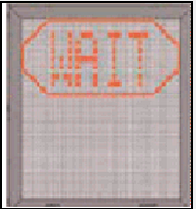 |
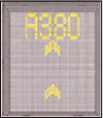
| 2 | CAPTURE The yellow scrolling arrows indicate that the system is activated and in capture mode, searching for an approaching aircraft. It shall be checked that the correct aircraft type is displayed. The lead-in line shall be followed.
|  |
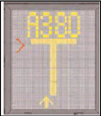
| 3 | TRACKING On successful capture of the aircraft, the yellow scrolling arrows are replaced by the yellow centre line indicator (Closing Rate Bar).
|  |
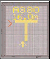
| 4 | CLOSING RATE Display of digital countdown starts when the aircraft is 20 meters from stop position.
|  |
| 5 | ALIGNED TO CENTRE The absence of any direction arrow indicates the aircraft is on the centre line.
| 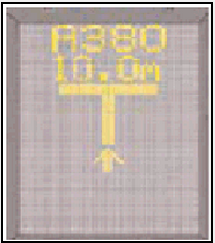 |
| 6 | SLOW (DECREASE SPEED) If the aircraft is approaching faster than the accepted speed, the system will show 'SLOW' as a warning to the pilot. | .PNG) |
| 7 | STOP POSITION REACHED When the correct stop-position is reached, the display will show 'STOP'. | 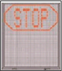 |
| 8 | DOCKING COMPLETED When the aircraft has parked, 'OK' will be displayed. | 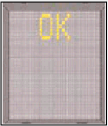 |
| 9 | OVERSHOOT If the aircraft overshot the stop-position, 'TOO FAR' will be displayed. | 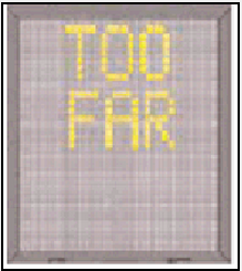 |
| 10 | STOP SHORT If the aircraft is found standing still but has not reached the intended stop-position, the message 'STOP OK' will be shown after a while. | 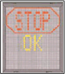 |
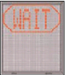
| 11 | WAIT If some object is blocking the view toward approaching aircraft or the detected aircraft is lost during docking close to STOP, the display will show 'WAIT'.
|  |
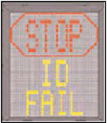
| 12 | AIRCRAFT VERIFICATION FAILURE During entry into the stand, the aircraft geometry is being checked. If, for any reason, aircraft verification is not made 12 M before the stop-position, the display will first show 'WAIT' and make a second verification check. If this fails 'STOP' and 'ID FAIL' will be displayed.
|  |
| 13 | SLOW (IN ABNORMAL SITUATIONS) This display can be shown for two reasons:
| .PNG) |
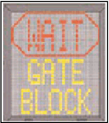
| 14 | GATE BLOCKED If an object is found blocking the view from the docking system to the planned stop position for the aircraft, the docking procedure will be halted with a 'WAIT' and 'GATE BLOCK' message. The docking procedure will resume as soon as the blocking object has been removed.
|  |
| 15 | VIEW BLOCKED If the view towards the approaching aircraft is hindered, for example internally in the unit on the laser lens or on the laser window by dirt, or another obstacle in the closest view area, the docking system will report a view blocked condition, i.e. ‘VIEW BLOCK’. Once the system is able to see the aircraft through the hinder, the message will be replaced by closing rate bar.
| 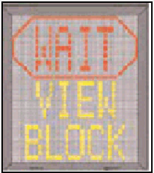 |
| 16 | SBU-STOP Any unrecoverable error during the docking procedure will generate a SBU (Safety Back Up) condition. The display will show 'STOP SBU' message.
| 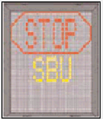 |
| 17 | TOO FAST If the aircraft approaches with a speed higher than the docking system can handle, the message 'STOP' and 'TOO FAST' will be displayed. The docking system must be re-started or the docking procedure completed by manual guidance. | 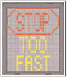 |
| 18 | EMERGENCY STOP Pilots should stop the aircraft immediately when ‘STOP’ is displayed. | 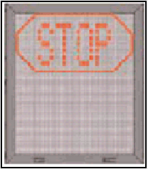 |
| 19 | CHOCKS ON 'CHOCK ON' will be displayed when the ground staff has put the chocks in front of the nose wheel and pressed the 'chocks on' button on the operator panel. | 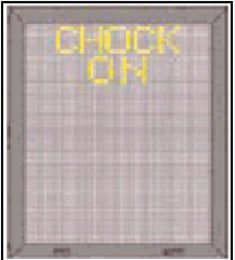 |
| 20 | ERROR If a system error occurs, the message 'ERROR' will be displayed with an error code. | 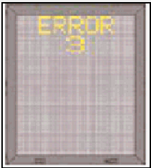 |
| 21 | SYSTEM BREAKDOWN / POWER FAILURE In case of a severe system failure or power failure, the display will go black. A manual backup procedure will be used for docking guidance. | 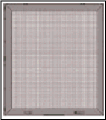 |
1.4 Stand docking procedures
| Item. | Procedure | Pilot Display |
|---|---|---|
| 1 | Aircraft Docking Activation | |
| 1.1 | Aircraft docking activation is performed by the operator. When the Docking system has been activated, the pilot display indicates ‘WAIT’ with red border. (At the operator panel: When the Docking system is ready to operate, the operator panel will show ‘SAFEDOCK SYSTEM’ followed by a status message. If the status is ‘READY’, the docking procedure can be initiated by tapping the Start Dock button. A ‘START DOCKING’ message appears, followed by the option ‘SELECT AIRCRAFT’. Or Manual Pause |  |
| 2 | Aircraft Capture and Guidance Workflow in VDGS Systems | |
| 2.1 | Capturing signals | |
| 2.1.1 | When the Docking system is in active mode and scanning for an approaching aircraft, the pilot display indicates capturing signals. Caution: The pilot must not proceed beyond the PBB, unless the capture signals have been superseded by the closing rate bar. | 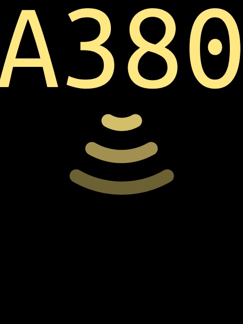 |
| 2.2 | Tracking | |
| 2.2.1 | On actively tracking and verifying the aircraft:
| 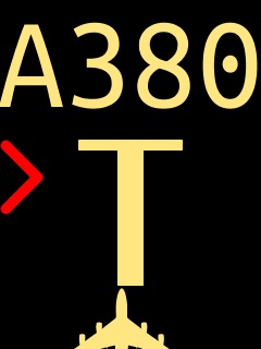 |
| 2.2.2 | On successful verification:
| 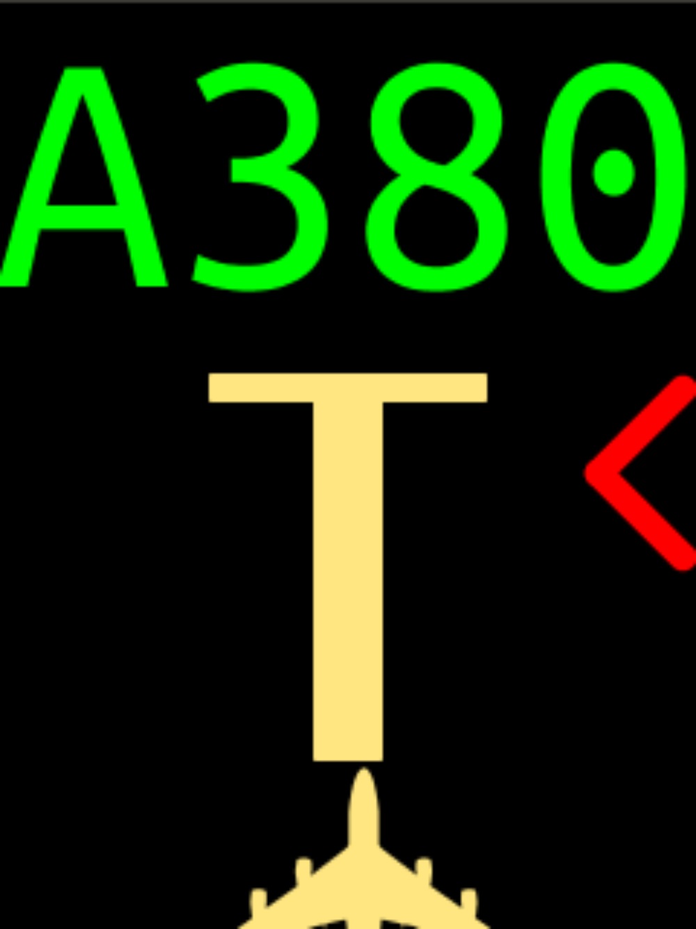 |
| 3 | Closing Rate | |
| 3.1 | The closing rate is the final countdown from a specific distance to the stop-position. A yellow vertical closing rate bar and centerline indicator appears, optionally with a digital countdown indication, depending on the configuration. The closing rate bar consists of a number of rows representing the remaining distance to go. Each row turns off in steps, beginning 20 meters from the stop-position as the aircraft approaches, illustrating a shrinking bar from the bottom. The given image illustrates the aircraft at the closing rate distance from stop-position, slightly left of the centerline. As the last row turns off, less than the interval for one row remains until the message ‘STOP’ appears. A digital countdown (option) shows the distance to stop numerically, with intervals depending on the configuration requirements. | 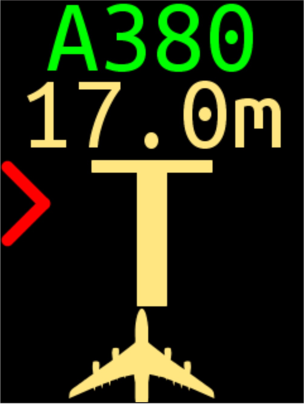  |
| 4 | Aligned to Center | |
| 4.1 | The given pilot display illustrates that the aircraft is at the displayed distance from the stop-position. The absence of a red flashing direction arrow indicates that the aircraft is aligned with the centerline. | |
| 5 | Slow (Decrease Speed) | |
| 5.1 | The Docking system is configured with a slowdown active zone. The limit speed for ‘SLOW’ down indication is configurable per aircraft type in the 0–10 range from the stop-position, with a default setting of 2 m/s. The limits further out are fixed: 10–20 m 3 m/s; more than 20 m 4 m/s. | .jpg) |
| 6 | Azimuth Guidance | |
| 6.1 | The aircraft is at the displayed distance from the stop-position. If the aircraft is not aligned to centerline, a yellow aircraft indicates an aircraft position relative to the centerline, and a red flashing direction arrow indicates the direction to turn. | 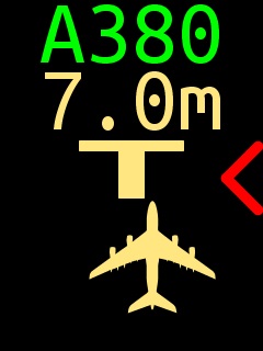 |
| 7 | Stop | |
| 7.1 | Stop-Position Reached When the correct stop-position is reached, the pilot display indicates ‘STOP’ with a red border. Or Emergency StopWhen the emergency stop button on the operator panel is activated, the pilot display indicates ‘STOP’ with red border. | |
| 8 | Docking Completed | |
| 8.1 | When the aircraft has parked, the pilot display indicates ‘OK’. |  |
| 9 | Hold Brake (Optional) | |
| 9.1 | If the Docking System is provided with optional support for information, the pilot display indicates ‘HOLD BRAKE’ as a remainder to the pilot. The message will remain on the pilot display until an operator overrides it via a CHOCKS ON message (See Item 10) or a Shutdown command. |  |
| 10 | Chocks On (Optional) | |
| 10.1 | The pilot display indicates 'CHOCKS ON' when the ground staff has put the chocks in front of the nose wheel and pressed the 'chocks on' button on the operator panel. |  |
| 11 | Bad Weather Conditions | |
| 11.1 | During heavy fog, rain or snow, the visibility of the Docking system can be reduced. When the system is activated and in capture mode, the pilot display disables the floating arrows and indicates aircraft ID followed by ‘SLOW’. As soon as the docking system detects the approaching aircraft, the vertical closing-rate bar appears. If the system has been configured in this mode, to make a shortened ID verification (check of engine position excluded), the yellow aircraft symbol blinks to give attention. | 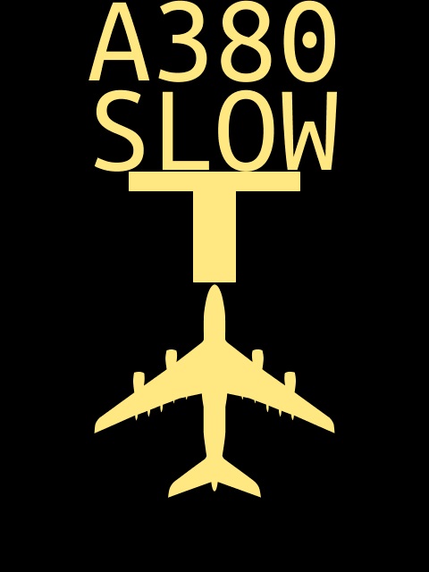 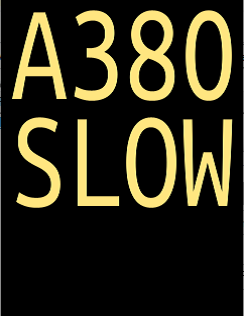 |
| 12 | Overshoot | |
| 12.1 | If the aircraft overshoots the stop-position with a configurable distance, the pilot display indicates ‘STOP’ with red borders and bars. It is then superseded by ‘TOO FAR’ after the aircraft comes to a complete stop. |  |
| 13 | Stop Short | |
| 13.1 | If the aircraft is found standing still, within a configurable distance up to 5 meters short of the stop-position, the pilot display indicates ‘STOP’ with red border followed by ‘OK’ after a configurable amount of time. |  |
| 14 | Failed Aircraft Identification – ID FAIL | |
| 14.1 | After capture of the aircraft, its geometry is checked against a stored profile. If, for any reason, aircraft verification is not confirmed 15 meters before the stop-position, the pilot display indicates ‘STOP’ with red border followed by ‘ID FAIL’. The pilot must not proceed beyond the PBB without manual guidance, unless the ‘WAIT’ message has been superseded by the ‘closing rate bar’. |  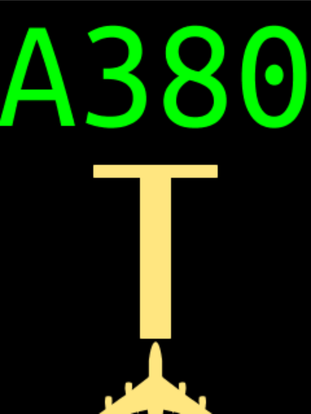 |
| 15 | Power Failure | |
| 15.1 | In case of a power failure, the pilot display will be completely black. A manual backup procedure must be used for docking guidance. |  |
| 16 | SBU Stop | |
| 16.1 | Any unrecoverable error during the docking procedure generates a Safety Backup (SBU) condition. The pilot display indicates ‘STOP’ with a red border followed by ‘SBU’. A manual backup procedure must be used for docking guidance. |  |
| 17 | Bridge In/Up Check | |
| 17.1 | The Docking system can be configured to require confirmation from various equipment, such as the correct positioning of the PBB, before a docking procedure may begin. For example, if the PBB is in an incorrect position, the pilot display indicates ‘BR IN’ and ‘Stand equipment’ interlock on the operator panel. |  |
| 18 | Gate Blocked | |
| 18.1 | If an object is found to be blocking the view from the Docking system unit towards the aircraft, and closer than the stop-position, this will be reported as a blocking object and the pilot display indicates ‘WAIT’ with red border followed by ‘GATE BLOCK’. |  |
| 19 | View Blocked | |
| 19.1 | If the view towards the approaching aircraft is hindered, the Docking system indicates ‘WAIT’ with red border followed by ‘VIEW BLOCK’. For example, hindered by dirt on the scanning unit window (<2.5 m to the laser). Once the system is able to see the aircraft through the dirt, the message is superseded with a closing rate bar. |  |
| 20 | Configuration Error | |
| 20.1 | Any error related to the system configuration that occurs during the docking operation generates an error message ‘ERR’ with red border will be indicated in both pilot display and operator panel. Or EmSource Missing When attempting to start a docking procedure with one or more emergency stop sources missing, the docking system will be aborted, and error message ‘ERR’ with red border will be indicated in both pilot display and operator panel. |  |
| 21 | Approach Monitoring (Optional) | |
| 21.1 | If the Docking system is provided with optional support for approach monitoring, and the aircraft is within the configured distance while outside the allowed approach region, the pilot display indicates ‘STOP’ with red border followed by “APPR ERR’. A manual backup procedure must be used for docking guidance. When the aircraft is in position after manual guidance, on the operator panel the Park On button may be taped on to detect the aircraft. If no aircraft is detected the approach error is again displayed. |  |
| 22 | LDM Recovery | |
| 22.1 | If the system detects an issue with incoming Laser Distance Meter (LDM) data, the pilot display indicates a yellow ‘WAIT’ and ‘LDM Recovery’ will be displayed on the operator panel while the system attempts to recover LDM function. |  |
| 23 | Undetected Object | |
| 23.1 | If an object that has not been picked up by the Lidar and it is detected by the Radar inside the critical area, the pilot display indicates ‘HOLD’ with red border, docking procedure will continue if the object moves out of the area. |  |
2 Areas in the AD where birds are observed
3 SURFACE MOVEMENT GUIDANCE, CONTROL SYSTEM AND MARKINGS
4 ADVISORY NOTICE TO ALL DEPARTING TRAFFIC
- VFR departures from OTBD - RWY 15 are independent from OTHH IFR traffic on the proviso that the VFR traffic climbs straight ahead to 700 FT, turns to the West before the upwind end of OTBD RWY 15. The VFR departure will state if it is unable to adhere to this route and will therefore be treated as per OTBD IFR departure.
- VFR departures from OTBD - RWY 33 are independent from OTHH IFR traffic on the proviso that the VFR traffic climbs straight ahead to 700 FT, turns to the West and remains South of OTP45. The VFR departure will state if it is unable to adhere to this route and will therefore be treated as per OTBD IFR departure.
OTHH AD 2.24 CHARTS RELATED TO AN AERODROME
* Contain multiple pages
| Chart Name | Page |
|---|---|
| AERODROME CHART - ICAO | AD2.OTHH-ADC.01 * |
| AERODROME GROUND MOVEMENT CHART - ICAO | AD2.OTHH-AGMC.01 |
| AIRCRAFT PARKING / DOCKING CHART - ICAO | AD2.OTHH-APDC.01 * |
| AERODROME OBSTACLE CHART ICAO - TYPE A RWY 16L/34R | AD2.OTHH-AOC-A.01 |
| AERODROME OBSTACLE CHART ICAO - TYPE A RWY 16R/34L | AD2.OTHH-AOC-A.03 |
| PRECISION APPROACH TERRAIN CHART ICAO - RWY 16L | AD2.OTHH-PATC.01 |
| PRECISION APPROACH TERRAIN CHART ICAO - RWY 34R | AD2.OTHH-PATC.03 |
| PRECISION APPROACH TERRAIN CHART ICAO - RWY 16R | AD2.OTHH-PATC.05 |
| PRECISION APPROACH TERRAIN CHART ICAO - RWY 34L | AD2.OTHH-PATC.07 |
| RWY 16L ALSEM 2M / KUPRO 1M / VAXIN 2M RNP CHART | AD2.OTHH-SID.01 * |
| RWY 16L ALVEN 2M / LUBET 1M / LUBET 1Y / TULUB 1M RNP CHART | AD2.OTHH-SID.03 * |
| RWY 16L KASIS TWO RADAR DEPARTURE RNP CHART | AD2.OTHH-SID.05 * |
| RWY 16R BUNDU 2C RNP CHART | AD2.OTHH-SID.07 * |
| RWY 16R DATRI 1C / ULIKA 1C RNP CHART | AD2.OTHH-SID.09 * |
| RWY 16R IVENA THREE RADAR DEPARTURE RNP CHART | AD2.OTHH-SID.11 * |
| RWY 16R LUBET 1C / TULUB 1C RNP CHART | AD2.OTHH-SID.13 * |
| RWY 34L DATRI 2W / ULIKA 2W RNP CHART | AD2.OTHH-SID.15 * |
| RWY 34L LUBET 2A (CCO) / TULUB 2A (CCO) RNP CHART | AD2.OTHH-SID.17 * |
| RWY 34L LUBET 2W RNP CHART | AD2.OTHH-SID.19 * |
| RWY 34L PARES THREE RADAR DEPARTURE RNP CHART | AD2.OTHH-SID.21 * |
| RWY 34L TULUB 2W RNP CHART | AD2.OTHH-SID.23 * |
| RWY 34L ULIKA 2A (CCO) RNP CHART | AD2.OTHH-SID.25 * |
| RWY 34R ALSEM 3E / BUNDU 3E / KUPRO 2E / VAXIN 3E RNP CHART | AD2.OTHH-SID.27 * |
| RWY 34R ALVEN 4E / LUBET 3E / LUBET 3Z / TULUB 3E RNP CHART | AD2.OTHH-SID.29 * |
| RWY 34R DEMBO FOUR RADAR DEPARTURE RNP CHART | AD2.OTHH-SID.31 * |
| RWY 16L/R ALKAN 1F / HAYYA 1F / HAYYA 1K / VEDED 1F RNP CHART | AD2.OTHH-STAR.01 * |
| RWY 16L/R ALKAN 2H / HAYYA 2H / VEDED 2H RNP CHART | AD2.OTHH-STAR.03 * |
| RWY 16L/R ALKAN 1P / HAYYA 1P / TOSNA 1T / VEDED 1P RNP CHART | AD2.OTHH-STAR.05 * |
| RWY 16L/R LAEEB 2F / LAEEB 2K / ORLEK 2F / TOSNA 2F / TOVOX 2F RNP CHART | AD2.OTHH-STAR.07 * |
| RWY 16L/R LAEEB 1P / ORLEK 1P / TOSNA 1P / TOVOX 2P RNP CHART | AD2.OTHH-STAR.09 * |
| RWY 34L/R ALKAN 2L / HAYYA 1J / HAYYA 2L / TOSNA 2J / VEDED 2L RNP CHART | AD2.OTHH-STAR.11 * |
| RWY 34L/R ALKAN 2R / HAYYA 2R / ORLEK 1R / TOSNA 2V / VEDED 2R RNP CHART | AD2.OTHH-STAR.13 * |
| RWY 34L/R ALKAN 2V / HAYYA 2V / VEDED 2V RNP CHART | AD2.OTHH-STAR.15 * |
| RWY 34L/R LAEEB 1R / TOSNA 2R / TOVOX 2R RNP CHART | AD2.OTHH-STAR.17 * |
| RWY 34L/R LAEEB 1J / LAEEB 1L / ORLEK 1L / TOSNA 2L / TOVOX 2L RNP CHART | AD2.OTHH-STAR.19 * |
| RWY 16L ILS CHART | AD2.OTHH-IAC.01 * |
| RWY 16L RNP CHART | AD2.OTHH-IAC.03 * |
| RWY 16R ILS CHART | AD2.OTHH-IAC.05 * |
| RWY 16R RNP CHART | AD2.OTHH-IAC.07 * |
| RWY 34L ILS CHART | AD2.OTHH-IAC.09 * |
| RWY 34L RNP CHART | AD2.OTHH-IAC.11 * |
| RWY 34R ILS CHART | AD2.OTHH-IAC.13 * |
| RWY 34R RNP CHART | AD2.OTHH-IAC.15 * |
| ATC SURVEILLANCE MINIMUM ALTITUDE CHART - ICAO | AD2.OTHH-ATCSMAC.01 |
| BIRD CONCENTRATION | AD2.OTHH-BCC.01 |
 QA-AD-2-OTHH-ADC.01-AERODROME-CHART-ICAO.pdf
* Contain multiple pages
OTHH AD 2.25 VISUAL SEGMENT SURFACE (VSS) PENETRATION
NIL